


Request Quote
(Ships tomorrow)
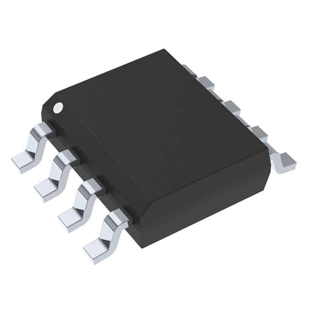
AO4456 N-Channel MOSFET 30V 20A Equivalent & Substitute Parts
Part Overview
The AO4456 is an N-Channel MOSFET manufactured by Alpha & Omega Semiconductor Inc., rated for 30V drain-to-source voltage with 20A continuous drain current in an 8-SOIC surface mount package. This device features a Schottky body diode and operates across a temperature range of -55°C to 150°C. The AO4456 is classified as obsolete, making equivalent and substitute parts necessary for ongoing design support and procurement.
Substiute Parts
Key Parameters
| Parameter | Value | Unit |
|---|---|---|
| Drain-to-Source Voltage (Vdss) | 30 | V |
| Continuous Drain Current (Id) @ 25°C | 20 | A |
| On-Resistance (Rds On) @ 20A, 10V | 4.6 | mOhm |
| Gate Threshold Voltage (Vgs(th)) @ 250µA | 2.4 | V |
| Gate Charge (Qg) @ 10V | 95 | nC |
| Input Capacitance (Ciss) @ 15V | 5185 | pF |
| Maximum Gate Voltage (Vgs) | ±12 | V |
| Power Dissipation (Max) | 3.1 | W |
| Operating Temperature Range | -55 to 150 | °C |
| Package Type | 8-SOIC | — |
| Mounting Type | Surface Mount | — |
Substitute Part Grouping Explanation
Substitution of the AO4456 is determined by the following critical electrical and mechanical parameters:
Primary Substitution Criteria:
- Drain-to-source voltage (Vdss) must equal or exceed 30V
- Continuous drain current (Id) must meet or exceed 20A at 25°C
- On-resistance (Rds On) must be compatible with circuit requirements
- Gate threshold voltage (Vgs(th)) must fall within acceptable switching range
- Package type must be 8-SOIC or equivalent surface mount footprint
- Operating temperature range must cover -55°C to 150°C minimum
Secondary Compatibility Factors:
- Gate charge (Qg) affects switching speed and driver requirements
- Input capacitance (Ciss) impacts gate drive circuit design
- Maximum gate voltage (Vgs) must accommodate driver output levels
- Power dissipation rating must support thermal management design
Substitute parts are grouped based on whether they meet the primary criteria for direct replacement or serve as functional alternatives with trade-offs in specific parameters.
Parameter Comparison
| Parameter | AO4456 | IRF7832TRPBF | IRF8736TRPBF | NTMS4802NR2G | RJK0349DSP-01#J0 | SQ4182EY-T1_GE3 |
|---|---|---|---|---|---|---|
| Manufacturer | Alpha & Omega | Infineon | Infineon | onsemi | Renesas | Vishay Siliconix |
| Vdss (V) | 30 | 30 | 30 | 30 | 30 | 30 |
| Id @ 25°C (A) | 20 | 20 | 18 | 11.1 | 20 | 32 |
| Rds On @ 10V (mOhm) | 4.6 | 4.0 | 4.8 | 4.0 | 3.8 | 3.8 |
| Vgs(th) (V) | 2.4 | 2.32 | 2.35 | 2.5 | — | 2.5 |
| Qg @ 10V (nC) | 95 | 51 | 26 | 36 | 25 | 110 |
| Ciss @ 15V (pF) | 5185 | 4310 | 2315 | 5300 | 3850 | 5400 |
| Vgs Max (V) | ±12 | ±20 | ±20 | ±20 | ±20 | ±20 |
| Power Dissipation (W) | 3.1 | 2.5 | 2.5 | 0.91 | 2.5 | 7.1 |
| Operating Temp Range (°C) | -55 to 150 | -55 to 155 | -55 to 150 | -55 to 150 | — | -55 to 175 |
| Package | 8-SOIC | 8-SO | 8-SO | 8-SOIC | 8-SOP | 8-SOIC |
| Product Status | Obsolete | Active | Active | Obsolete | Active | Active |
| RoHS Status | — | ROHS3 Compliant | ROHS3 Compliant | ROHS3 Compliant | ROHS3 Compliant | ROHS3 Compliant |
Engineering Selection Recommendations
Direct Replacement (Highest Compatibility):
The IRF7832TRPBF from Infineon Technologies is the primary recommended substitute. It matches the AO4456 in all critical electrical parameters: 30V Vdss, 20A continuous drain current, and 8-SOIC package footprint. The IRF7832TRPBF features lower gate charge (51 nC versus 95 nC), which reduces gate drive power requirements. This device is in active production status with ROHS3 compliance and unlimited moisture sensitivity level, ensuring long-term availability and regulatory compliance.
Secondary Replacement (Functional Equivalent with Trade-offs):
The RJK0349DSP-01#J0 from Renesas Electronics Corporation provides equivalent electrical performance with 30V Vdss and 20A continuous drain current. This device offers superior on-resistance (3.8 mOhm) and lower gate charge (25 nC), improving efficiency and switching characteristics. The 8-SOP package maintains mechanical compatibility with 8-SOIC footprints. Active production status and ROHS3 compliance support long-term design viability.
Higher Current Alternative:
The SQ4182EY-T1_GE3 from Vishay Siliconix exceeds the AO4456 specifications with 32A continuous drain current and 7.1W power dissipation, providing design margin for higher-load applications. This device is AEC-Q101 qualified for automotive applications and operates to 175°C, extending thermal operating range. The trade-off is higher gate charge (110 nC), requiring more robust gate drive circuitry.
Lower Current Alternative (Not Recommended for Direct Replacement):
The NTMS4802NR2G from onsemi is rated for only 11.1A continuous drain current, falling below the AO4456 specification of 20A. This device is suitable only for applications with reduced current requirements and is classified as obsolete.
Marginal Current Alternative:
The IRF8736TRPBF from Infineon Technologies is rated for 18A continuous drain current, which is 2A below the AO4456 specification. This device is acceptable only for applications where the actual operating current does not exceed 18A. The significantly lower gate charge (26 nC) and input capacitance (2315 pF) provide switching speed advantages if current derating is acceptable.
Compliance and Availability:
All active-status substitutes (IRF7832TRPBF, RJK0349DSP-01#J0, SQ4182EY-T1_GE3) are ROHS3 compliant with REACH unaffected status. Inventory levels are substantial across all recommended alternatives, supporting production requirements.
Frequently Asked Questions (FAQ)
Q: Can the IRF7832TRPBF directly replace the AO4456 without circuit modifications?
A: Yes. The IRF7832TRPBF matches the AO4456 in Vdss (30V), Id (20A), and package (8-SOIC). The lower gate charge (51 nC versus 95 nC) may reduce gate drive power consumption but does not require circuit changes. Verify gate driver output voltage compatibility with the ±20V Vgs maximum rating.
Q: What is the impact of lower gate charge in substitute devices?
A: Lower gate charge reduces the energy required to switch the MOSFET on and off, decreasing gate driver power dissipation and potentially allowing faster switching speeds. This is a beneficial characteristic that does not compromise compatibility. Existing gate drive circuits will function correctly with lower gate charge devices.
Q: Why is the NTMS4802NR2G not recommended as a direct replacement?
A: The NTMS4802NR2G is rated for 11.1A continuous drain current, which is 8.9A below the AO4456 specification of 20A. This device cannot safely handle the full 20A load and is suitable only for applications with reduced current requirements. Additionally, it is classified as obsolete.
Q: Are 8-SO and 8-SOP packages mechanically compatible with 8-SOIC?
A: The 8-SO, 8-SOP, and 8-SOIC packages share the same 0.154-inch (3.90 mm) width and pin pitch, making them mechanically and electrically compatible on standard PCB layouts. Verify specific package dimensions with manufacturer datasheets if tight board spacing is a constraint.
Q: What is the significance of the SQ4182EY-T1_GE3 AEC-Q101 qualification?
A: AEC-Q101 qualification indicates the device meets automotive industry reliability and quality standards. This qualification is relevant only if the application requires automotive-grade components. For non-automotive applications, this qualification provides no functional benefit but confirms rigorous testing and quality control.
Q: Can the IRF8736TRPBF be used in applications requiring 20A continuous current?
A: The IRF8736TRPBF is rated for 18A continuous drain current. Using this device in applications requiring 20A continuous current exceeds its specification and risks thermal runaway and device failure. This device is acceptable only if the actual operating current does not exceed 18A.
Q: How do I verify gate driver compatibility with substitute MOSFETs?
A: Confirm that the gate driver output voltage range accommodates the substitute device's maximum gate voltage (Vgs Max). The AO4456 specifies ±12V, while all recommended substitutes specify ±20V. Existing drivers rated for ±12V will operate safely with ±20V-rated devices. Verify gate charge specifications to ensure the driver can deliver required charge within acceptable switching times.
Q: What is the impact of higher power dissipation in the SQ4182EY-T1_GE3?
A: The SQ4182EY-T1_GE3 is rated for 7.1W power dissipation compared to the AO4456's 3.1W. Higher power dissipation requires more effective thermal management through increased copper area, thermal vias, or heat sinking. This is a design consideration, not a compatibility issue, and allows the device to handle higher current loads with better thermal margin.
Q: Are all substitute parts ROHS3 compliant?
A: All active-status substitute parts (IRF7832TRPBF, RJK0349DSP-01#J0, SQ4182EY-T1_GE3) are ROHS3 compliant. The obsolete NTMS4802NR2G is also ROHS3 compliant. ROHS3 compliance ensures the devices meet environmental and regulatory requirements for lead-free manufacturing.
Alternative Parts

SJ6012L2TP
Littelfuse Inc.
6 Alternative Parts

JMK107BBJ476MA-RE
Taiyo Yuden
10 Alternative Parts

GMK107BBJ475MA-T
Taiyo Yuden
5 Alternative Parts
SJ6020N2ARP
Littelfuse Inc.
3 Alternative Parts
SJ6025R2ATP
Littelfuse Inc.
4 Alternative Parts

2474-05L
API Delevan Inc.
1 Alternative Parts

4590R-684K
API Delevan Inc.
1 Alternative Parts

CM6560R-334
API Delevan Inc.
1 Alternative Parts

CM6460-104
API Delevan Inc.
1 Alternative Parts

5526-12
API Delevan Inc.
1 Alternative Parts