


Request Quote
(Ships tomorrow)
AISC-0402F-70NK-T Equivalent & Substitute Parts
Part Overview
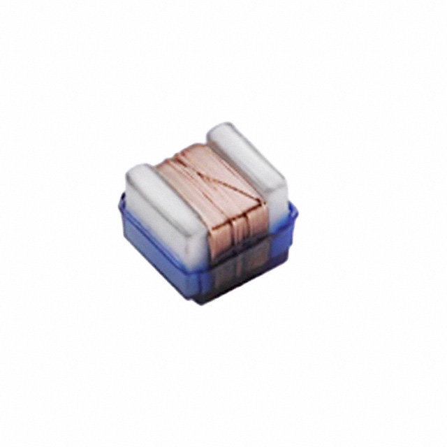
The AISC-0402F-70NK-T is a 70 nH unshielded drum core wirewound inductor manufactured by Abracon LLC in a 0402 (1005 Metric) surface mount package. This component is rated for 820 mA continuous current with a maximum DC resistance of 120 mOhm and operates across the temperature range of -40°C to 85°C. The part is classified as obsolete, necessitating identification of functionally equivalent alternatives for ongoing design requirements and production continuity.
Substiute Parts
Key Parameters
| Parameter | Value | Unit |
|---|---|---|
| Inductance | 70 | nH |
| Tolerance | ±10% | % |
| Current Rating | 820 | mA |
| DC Resistance (Max) | 120 | mOhm |
| Package / Case | 0402 (1005 Metric) | — |
| Mounting Type | Surface Mount | — |
| Operating Temperature Range | -40°C to 85°C | °C |
| Shielding | Unshielded | — |
| RoHS Status | ROHS3 Compliant | — |
Substitute Part Grouping Explanation
Substitution of the AISC-0402F-70NK-T is determined by the following critical parameters:
Package Compatibility: Both the main part and substitute must use the 0402 (1005 Metric) surface mount package to ensure mechanical and electrical compatibility with existing PCB layouts and assembly processes.
Inductance Value: The substitute AISC-0402HP-68NJ-T provides 68 nH inductance, which falls within the tolerance band of the original 70 nH specification (±10% tolerance = 63 nH to 77 nH range). This inductance value is functionally equivalent for circuit applications.
Current Rating: The substitute part is rated for 320 mA continuous current, which is lower than the original 820 mA rating. This parameter difference restricts substitution to applications where the circuit current demand does not exceed 320 mA.
DC Resistance: The substitute exhibits 950 mOhm maximum DC resistance compared to the original 120 mOhm maximum. This represents a significant increase in series resistance and must be evaluated against circuit performance requirements.
Unshielded Configuration: Both parts maintain unshielded drum core construction, preserving electromagnetic characteristics for applications not requiring shielding.
Regulatory Compliance: Both parts maintain ROHS3 compliance and REACH unaffected status, ensuring regulatory continuity.
Parameter Comparison
| Parameter | AISC-0402F-70NK-T (Main) | AISC-0402HP-68NJ-T (Substitute) | Compatibility Notes |
|---|---|---|---|
| Inductance | 70 nH | 68 nH | Within ±10% tolerance band of main part |
| Inductance Tolerance | ±10% | ±5% | Substitute offers tighter tolerance |
| Current Rating | 820 mA | 320 mA | Substitute rated for lower current; application-dependent |
| DC Resistance (Max) | 120 mOhm | 950 mOhm | Substitute exhibits significantly higher series resistance |
| Package / Case | 0402 (1005 Metric) | 0402 (1005 Metric) | Identical package; direct PCB compatibility |
| Mounting Type | Surface Mount | Surface Mount | Compatible with existing assembly processes |
| Operating Temperature Range | -40°C to 85°C | -40°C to 125°C | Substitute supports extended upper temperature limit |
| Shielding | Unshielded | Unshielded | Identical shielding configuration |
| Frequency - Self Resonant | 1.3 GHz | 1.84 GHz | Substitute exhibits higher self-resonant frequency |
| RoHS Status | ROHS3 Compliant | ROHS3 Compliant | Regulatory compliance maintained |
| Product Status | Obsolete | Active | Substitute is in active production |
Engineering Selection Recommendations
The AISC-0402HP-68NJ-T serves as a functional substitute for the obsolete AISC-0402F-70NK-T based on the following engineering criteria:
Package and Mounting Compatibility: Both components utilize identical 0402 (1005 Metric) surface mount packaging, ensuring direct compatibility with existing PCB designs and automated assembly equipment without layout modifications.
Inductance Equivalence: The 68 nH inductance of the substitute falls within the ±10% tolerance specification of the original 70 nH part, providing functional equivalence for circuit inductance requirements.
Regulatory and Compliance Status: Both parts maintain ROHS3 compliance and REACH unaffected status. The substitute is in active production status, ensuring long-term availability and supply chain continuity compared to the obsolete main part.
Application-Specific Constraints: Selection of the substitute requires verification that circuit current demands do not exceed 320 mA, as this represents a significant reduction from the original 820 mA rating. Additionally, the increased DC resistance of 950 mOhm (versus 120 mOhm) must be evaluated against circuit performance specifications, particularly in applications sensitive to series resistance effects.
Temperature Performance: The substitute supports an extended operating temperature range to 125°C, providing additional thermal margin for applications operating at elevated temperatures.
Frequently Asked Questions (FAQ)
Q: Can the AISC-0402HP-68NJ-T directly replace the AISC-0402F-70NK-T in all applications?
A: Direct substitution is limited by current rating and DC resistance differences. The substitute is suitable only for applications where circuit current remains below 320 mA and where the increased series resistance (950 mOhm versus 120 mOhm) does not degrade circuit performance. Inductance equivalence is confirmed within tolerance specifications.
Q: What is the inductance tolerance relationship between these parts?
A: The main part specifies ±10% tolerance (63 nH to 77 nH range), while the substitute specifies ±5% tolerance (64.6 nH to 71.4 nH range). The substitute's 68 nH nominal value falls within the main part's tolerance band, confirming inductance compatibility.
Q: Are there package or mounting differences between these components?
A: Both components use identical 0402 (1005 Metric) surface mount packaging with equivalent physical dimensions and mounting characteristics. No PCB layout or assembly process modifications are required for substitution.
Q: How does the DC resistance difference affect circuit performance?
A: The substitute exhibits 950 mOhm maximum DC resistance compared to 120 mOhm for the original part. This 7.9x increase in series resistance introduces additional voltage drop and power dissipation. Circuit performance impact depends on application-specific requirements and operating current levels.
Q: What is the significance of the different self-resonant frequencies?
A: The main part exhibits a self-resonant frequency of 1.3 GHz, while the substitute operates at 1.84 GHz. This difference reflects variations in core material and construction. Applications operating near these frequency ranges require evaluation to ensure the substitute's higher self-resonant frequency remains compatible with circuit requirements.
Q: Why is the substitute rated for lower current despite using the same package?
A: Current rating differences result from core material selection and thermal design. The substitute uses ceramic core material versus ferrite in the main part, affecting current handling capacity and thermal characteristics. The 320 mA rating represents the maximum continuous current before saturation or thermal limits are exceeded.
Q: Are both parts compliant with current regulatory requirements?
A: Both components maintain ROHS3 compliance and REACH unaffected status. The substitute, being in active production, ensures ongoing compliance with evolving regulatory standards and supply chain continuity.
Alternative Parts

SJ6012L2TP
Littelfuse Inc.
6 Alternative Parts

JMK107BBJ476MA-RE
Taiyo Yuden
10 Alternative Parts

GMK107BBJ475MA-T
Taiyo Yuden
5 Alternative Parts
SJ6020N2ARP
Littelfuse Inc.
3 Alternative Parts
SJ6025R2ATP
Littelfuse Inc.
4 Alternative Parts

2474-05L
API Delevan Inc.
1 Alternative Parts

4590R-684K
API Delevan Inc.
1 Alternative Parts

CM6560R-334
API Delevan Inc.
1 Alternative Parts

CM6460-104
API Delevan Inc.
1 Alternative Parts

5526-12
API Delevan Inc.
1 Alternative Parts