


Request Quote
(Ships tomorrow)
AD621BNZ Equivalent & Substitute Parts
Part Overview
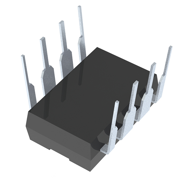
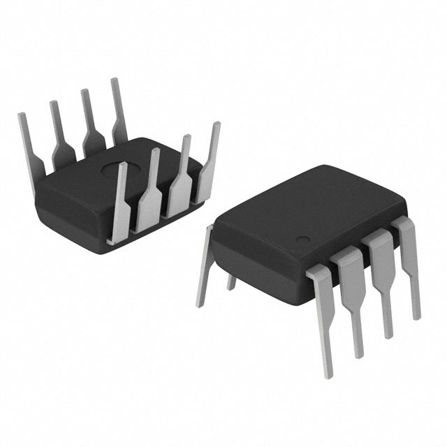
The AD621BNZ is an instrumentation amplifier manufactured by Analog Devices Inc., housed in an 8-PDIP through-hole package. This single-circuit linear amplifier operates across a wide supply voltage range of 4.6 V to 36 V and maintains active product status with 3127 units in stock. The device is ROHS3 compliant with unlimited moisture sensitivity rating (MSL 1).
Substitute parts become necessary when the AD621BNZ reaches end-of-life status, inventory depletion, or when application requirements demand alternative electrical characteristics such as improved slew rate, reduced input bias current, or enhanced bandwidth performance.
Substiute Parts
Key Parameters
| Parameter | Value | Unit |
|---|---|---|
| Amplifier Type | Instrumentation | — |
| Number of Circuits | 1 | — |
| Slew Rate | 1.2 | V/µs |
| -3dB Bandwidth | 800 | kHz |
| Current - Input Bias | 500 | pA |
| Voltage - Input Offset | 50 | µV |
| Current - Supply | 900 | µA |
| Current - Output / Channel | 18 | mA |
| Voltage - Supply Span (Min) | 4.6 | V |
| Voltage - Supply Span (Max) | 36 | V |
| Operating Temperature Range | -40 to 85 | °C |
| Package / Case | 8-DIP (0.300", 7.62mm) | — |
| Mounting Type | Through Hole | — |
| RoHS Status | ROHS3 Compliant | — |
Substitute Part Grouping Explanation
Substitution compatibility for the AD621BNZ is determined by the following critical parameters:
Package and Mounting Compatibility: All substitute parts must use 8-DIP (0.300", 7.62mm) through-hole packaging to ensure direct PCB compatibility without layout modifications.
Supply Voltage Range: Substitute parts must support the full 4.6 V to 36 V supply span or a compatible subset that covers the application's operating voltage window.
Operating Temperature Range: The AD621BNZ operates from -40°C to 85°C. Substitutes with narrower temperature ranges (0°C to 70°C) are acceptable only when the application does not require extended low-temperature operation.
Instrumentation Amplifier Classification: All substitutes must be single-circuit instrumentation amplifiers with identical functional topology.
Electrical Performance Parameters: Slew rate, bandwidth, input bias current, input offset voltage, and output current capacity determine functional equivalence. Substitutes with equal or superior performance in these parameters maintain or improve circuit behavior.
Compliance and Certification: ROHS3 compliance and REACH unaffected status ensure regulatory alignment with the original part.
Parameter Comparison
| Part Number | Manufacturer | Slew Rate (V/µs) | Bandwidth (kHz) | Input Bias (pA) | Input Offset (µV) | Supply Current (µA) | Output Current (mA) | Temp Range (°C) | Product Status |
|---|---|---|---|---|---|---|---|---|---|
| AD621BNZ | Analog Devices | 1.2 | 800 | 500 | 50 | 900 | 18 | -40 to 85 | Active |
| LT1167IN8#PBF | Analog Devices | 1.2 | 1000 | 80 | 20 | 900 | 27 | -40 to 85 | Active |
| LT1168ACN8#PBF | Analog Devices | 0.5 | 400 | 40 | 15 | 350 | 32 | 0 to 70 | Active |
| LT1920CN8#PBF | Analog Devices | 1.2 | 1000 | 500 | 30 | 900 | — | 0 to 70 | Active |
| INA114AP | Texas Instruments | 0.6 | 1000 | 500 | 25 | 2200 | 20 | -40 to 85 | Active |
| INA118P | Texas Instruments | 0.9 | 800 | 1000 | 25 | 350 | 12 | -40 to 85 | Active |
| INA121P | Texas Instruments | 0.7 | 600 | 4 | 200 | 450 | 14 | -40 to 85 | Active |
| INA128PA | Texas Instruments | 4.0 | 1300 | 2 | 25 | 700 | 15 | -40 to 85 | Last Time Buy |
| INA129P | Burr Brown | 4.0 | 1300 | 20000 | 10 | 700 | 15 | -40 to 85 | Active |
| INA129PA | Texas Instruments | 4.0 | 1300 | 2 | 25 | 700 | 15 | -40 to 85 | Active |
Engineering Selection Recommendations
Primary Substitutes (Analog Devices Ecosystem):
LT1167IN8#PBF and LT1920CN8#PBF are direct Analog Devices alternatives with matching 1.2 V/µs slew rate and 900 µA supply current. LT1167IN8#PBF maintains the full -40°C to 85°C temperature range and offers improved input offset voltage (20 µV versus 50 µV). LT1920CN8#PBF operates within a narrower 0°C to 70°C range and is suitable for commercial-grade applications.
LT1168ACN8#PBF provides reduced power consumption (350 µA) and lower input offset voltage (15 µV) but operates at reduced slew rate (0.5 V/µs) and narrower bandwidth (400 kHz), making it suitable for low-power, low-frequency applications within the 0°C to 70°C range.
Secondary Substitutes (Texas Instruments INA Series):
INA114AP maintains full temperature range (-40°C to 85°C) with 1 MHz bandwidth and 25 µV input offset voltage. Higher supply current (2.2 mA) is a trade-off for improved performance metrics.
INA128PA and INA129PA deliver superior slew rate (4.0 V/µs) and bandwidth (1.3 MHz) with excellent input offset voltage (25 µV and 10 µV respectively). INA128PA carries Last Time Buy status, indicating limited future availability. Both maintain -40°C to 85°C operation.
INA121P offers extremely low input bias current (4 pA) with full temperature range support, suitable for high-impedance input applications, though bandwidth is reduced to 600 kHz.
INA118P provides the lowest supply current (350 µA) and operates across extended supply range (2.7 V to 36 V), though input bias current is elevated at 1 nA.
Compliance Considerations:
All recommended substitutes maintain ROHS3 compliance and REACH unaffected status. Moisture sensitivity level (MSL 1) is consistent across all parts, indicating unlimited shelf life under standard storage conditions.
Frequently Asked Questions (FAQ)
Q: Can LT1168ACN8#PBF replace AD621BNZ in all applications?
A: LT1168ACN8#PBF is mechanically and electrically compatible within the 0°C to 70°C operating range. Applications requiring -40°C operation must use alternatives such as LT1167IN8#PBF or INA114AP. The reduced slew rate (0.5 V/µs versus 1.2 V/µs) and narrower bandwidth (400 kHz versus 800 kHz) limit use to low-frequency signal conditioning.
Q: What is the primary difference between INA128PA and INA129PA?
A: Both parts offer identical electrical performance (4.0 V/µs slew rate, 1.3 MHz bandwidth, -40°C to 85°C operation). INA128PA carries Last Time Buy status, indicating production discontinuation. INA129PA is actively produced by Texas Instruments and represents the recommended long-term substitute.
Q: Does package compatibility guarantee functional substitution?
A: Package compatibility (8-DIP through-hole) ensures mechanical fit and PCB mounting without layout changes. Functional substitution additionally requires compatible supply voltage range, operating temperature range, and electrical performance parameters. Verify application-specific requirements for slew rate, bandwidth, and input bias current before selection.
Q: Why does INA121P have such low input bias current?
A: INA121P uses JFET input stage technology, resulting in 4 pA input bias current compared to 500 pA in AD621BNZ. This characteristic makes INA121P suitable for high-impedance sensor interfaces where input bias current introduces unacceptable measurement error. Trade-offs include reduced bandwidth (600 kHz) and elevated input offset voltage (200 µV).
Q: Are all substitutes ROHS3 compliant?
A: All listed substitutes maintain ROHS3 compliance and REACH unaffected status, ensuring regulatory alignment with the original AD621BNZ for applications subject to environmental restrictions.
Q: What supply current differences should influence part selection?
A: AD621BNZ draws 900 µA at nominal operation. LT1168ACN8#PBF and INA118P reduce this to 350 µA, beneficial for battery-powered applications. INA114AP increases supply current to 2.2 mA. INA128PA and INA129PA operate at 700 µA. Selection depends on power budget constraints and thermal management requirements.
Q: Can substitutes with higher slew rate cause circuit instability?
A: Higher slew rate (4.0 V/µs in INA128PA and INA129PA versus 1.2 V/µs in AD621BNZ) improves transient response and high-frequency performance. No instability results from increased slew rate capability. Verify that feedback network stability margins remain adequate for the selected part's gain-bandwidth product.
Alternative Parts

SJ6012L2TP
Littelfuse Inc.
6 Alternative Parts

JMK107BBJ476MA-RE
Taiyo Yuden
10 Alternative Parts

GMK107BBJ475MA-T
Taiyo Yuden
5 Alternative Parts
SJ6020N2ARP
Littelfuse Inc.
3 Alternative Parts
SJ6025R2ATP
Littelfuse Inc.
4 Alternative Parts

2474-05L
API Delevan Inc.
1 Alternative Parts

4590R-684K
API Delevan Inc.
1 Alternative Parts

CM6560R-334
API Delevan Inc.
1 Alternative Parts

CM6460-104
API Delevan Inc.
1 Alternative Parts

5526-12
API Delevan Inc.
1 Alternative Parts