


Request Quote
(Ships tomorrow)
Antenova A6150 RF Antenna — Equivalent & Substitute Parts
Part Overview
The Antenova A6150 is a 2.4GHz PCB trace RF antenna designed for Bluetooth, WLAN, and Zigbee™ applications operating in the 2.4GHz to 2.5GHz frequency band. This component is classified as obsolete, making identification of functionally equivalent alternatives necessary for ongoing design support and production continuity. Substitute parts must maintain compatibility with the same frequency band, RF standards, and surface mount assembly process while meeting the electrical performance requirements of the original design.
Substiute Parts
Key Parameters
| Parameter | A6150 Specification |
|---|---|
| Frequency Range | 2.4GHz ~ 2.5GHz |
| Frequency Group | UHF (2GHz ~ 3GHz) |
| RF Family/Standard | 802.15.4, Bluetooth, WiFi |
| Antenna Type | PCB Trace |
| Gain | 1dBi |
| VSWR | 1.9 |
| Return Loss | -10dB |
| Mounting Type | Surface Mount |
| Termination | Solder |
| Height (Max) | 0.043" (1.10mm) |
| Moisture Sensitivity Level | 1 (Unlimited) |
| Product Status | Obsolete |
Substitute Part Grouping Explanation
Substitution eligibility for the A6150 is determined by the following criteria:
Primary Compatibility Requirements:
- Frequency range overlap within 2.4GHz ~ 2.5GHz band
- RF standards support for at least one of: 802.15.4, Bluetooth, or WiFi
- Surface mount solder termination
- UHF frequency group classification
Secondary Considerations:
- Antenna type (PCB trace, chip, or ceramic patch)
- Physical height constraints for PCB integration
- VSWR and return loss performance
- Moisture sensitivity level and compliance certifications
Substitute parts are grouped by antenna type and electrical performance characteristics. Parts meeting the primary requirements are considered functionally equivalent for the 2.4GHz band, though antenna type and gain differences may require PCB layout or impedance matching adjustments.
Parameter Comparison
| Parameter | A6150 (Antenova) | SR42W001 (Antenova) | SWLP.2450.12.4.B.02 (Taoglas) | WLA.01 (Taoglas) | WLP.2450.25.4.A.02 (Taoglas) |
|---|---|---|---|---|---|
| Frequency Range | 2.4GHz ~ 2.5GHz | 2.4GHz ~ 2.5GHz, 4.9GHz ~ 5.9GHz | 2.4GHz ~ 2.5GHz | 2.4GHz ~ 2.5GHz | 2.44GHz ~ 2.525GHz |
| RF Standards | 802.15.4, Bluetooth, WiFi | WiFi | 802.15.4, WiFi | 802.15.4, Bluetooth, WiFi | 802.15.4, Bluetooth, WiFi |
| Antenna Type | PCB Trace | Chip | Ceramic Patch | Chip | Ceramic Patch |
| Gain | 1dBi | 2dBi | 2dBi | 2.5dBi | 5dBic |
| VSWR | 1.9 | 1.5 | 3 | 2 | 2 |
| Return Loss | -10dB | -12dB | — | — | -10dB |
| Mounting Type | Surface Mount | Surface Mount | Surface Mount | Surface Mount | Adhesive |
| Termination | Solder | Solder | Solder | Solder | Pin |
| Height (Max) | 0.043" (1.10mm) | 0.031" (0.80mm) | 0.157" (4.00mm) | 0.020" (0.50mm) | 0.197" (5.00mm) |
| MSL Rating | 1 (Unlimited) | 1 (Unlimited) | 3 (168 Hours) | 3 (168 Hours) | 3 (168 Hours) |
| Product Status | Obsolete | Active | Active | Active | Active |
| RoHS Status | — | RoHS Compliant | ROHS3 Compliant | ROHS3 Compliant | ROHS3 Compliant |
Engineering Selection Recommendations
SR42W001 (Antenova): Active product with dual-band capability (2.4GHz and 5.4GHz). Maintains Antenova manufacturer continuity. Chip antenna type requires different PCB footprint than the original PCB trace design. Superior VSWR (1.5) and return loss (-12dB) performance. MSL rating of 1 matches the original part. Suitable for designs requiring enhanced RF performance or future 5GHz band support.
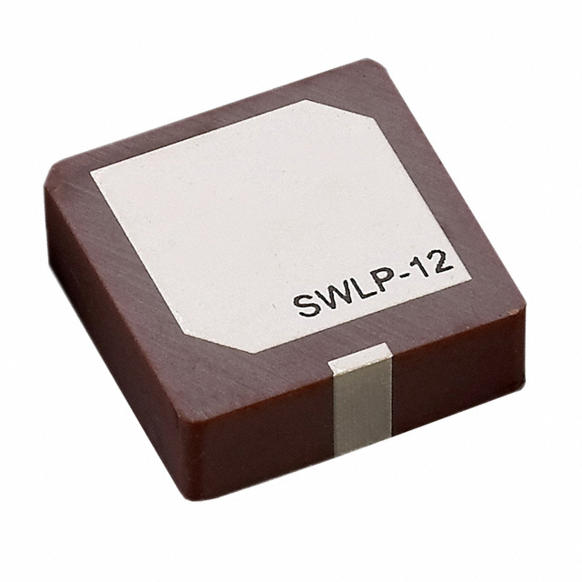
SWLP.2450.12.4.B.02 (Taoglas Limited): Active product with ceramic patch construction. Maintains single-band 2.4GHz operation and supports 802.15.4 and WiFi standards. Significantly taller profile (4.00mm) compared to original (1.10mm) may present PCB layout constraints. VSWR of 3 indicates higher impedance mismatch than original. MSL rating of 3 requires controlled storage conditions. Suitable for applications where height is not a limiting factor and higher gain (2dBi) is beneficial.
WLA.01 (Taoglas Limited): Active product with chip antenna construction. Maintains full RF standard compatibility (802.15.4, Bluetooth, WiFi). Lowest profile (0.50mm) among all substitutes, enabling space-constrained designs. Highest gain (2.5dBi) provides improved link budget. MSL rating of 3 requires moisture control during assembly. Suitable for compact form factor requirements with enhanced RF performance.
WLP.2450.25.4.A.02 (Taoglas Limited): Active product with ceramic patch construction and pin adhesive termination. Highest gain (5dBic) among all options. Frequency range (2.44GHz ~ 2.525GHz) is narrower than original specification. Pin adhesive mounting differs from solder termination, requiring design modification. Tallest profile (5.00mm) presents significant PCB integration challenges. MSL rating of 3 requires controlled storage. Suitable only for applications where high gain and adhesive mounting are design requirements.
Frequently Asked Questions (FAQ)
Q: Can SR42W001 replace A6150 in existing designs without modification? A: SR42W001 is functionally equivalent for 2.4GHz operation but uses chip antenna construction instead of PCB trace. PCB footprint and layout modifications are required. The improved VSWR and return loss may eliminate need for impedance matching adjustments present in original design.
Q: What is the primary difference between chip and ceramic patch antenna substitutes? A: Chip antennas (SR42W001, WLA.01) occupy minimal PCB space with heights under 1mm, suitable for compact designs. Ceramic patch antennas (SWLP.2450.12.4.B.02, WLP.2450.25.4.A.02) provide higher gain but require 4mm to 5mm height clearance. Selection depends on available PCB real estate and required RF performance.
Q: Does MSL rating affect substitute part selection? A: Yes. A6150 has MSL 1 (unlimited moisture exposure tolerance). Substitutes with MSL 3 (SWLP.2450.12.4.B.02, WLA.01, WLP.2450.25.4.A.02) require controlled storage at ≤30% relative humidity and must be used within 168 hours of package opening. Manufacturing processes must accommodate these constraints.
Q: Which substitute offers the closest electrical performance match to A6150? A: SR42W001 provides the closest match with VSWR of 1.5 (vs. 1.9) and return loss of -12dB (vs. -10dB), indicating superior impedance matching. WLA.01 offers comparable performance with VSWR of 2 and maintains full RF standard compatibility.
Q: Can WLP.2450.25.4.A.02 be used as a direct replacement? A: No. WLP.2450.25.4.A.02 uses pin adhesive termination instead of solder, requiring significant PCB design changes. The 5.00mm height may exceed available clearance in existing designs. This part is suitable only for new designs where adhesive mounting is acceptable.
Q: Are all substitutes RoHS compliant? A: SR42W001 is RoHS Compliant. SWLP.2450.12.4.B.02, WLA.01, and WLP.2450.25.4.A.02 are ROHS3 Compliant. All meet current environmental compliance requirements. Original A6150 compliance status is not specified in available documentation.
Alternative Parts

SJ6012L2TP
Littelfuse Inc.
6 Alternative Parts

JMK107BBJ476MA-RE
Taiyo Yuden
10 Alternative Parts

GMK107BBJ475MA-T
Taiyo Yuden
5 Alternative Parts
SJ6020N2ARP
Littelfuse Inc.
3 Alternative Parts
SJ6025R2ATP
Littelfuse Inc.
4 Alternative Parts

2474-05L
API Delevan Inc.
1 Alternative Parts

4590R-684K
API Delevan Inc.
1 Alternative Parts

CM6560R-334
API Delevan Inc.
1 Alternative Parts

CM6460-104
API Delevan Inc.
1 Alternative Parts

5526-12
API Delevan Inc.
1 Alternative Parts