


Request Quote
(Ships tomorrow)
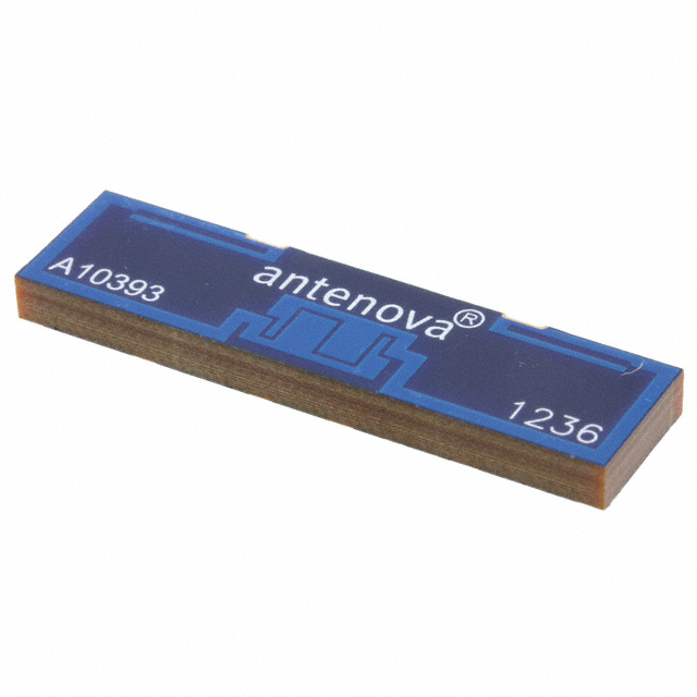
Antenova A10393 RF Antenna - Equivalent & Substitute Parts
Part Overview
The Antenova A10393 is a PCB trace RF antenna designed for multi-band cellular applications including GSM, UMTS, and WCDMA standards. Operating across five frequency bands (850MHz, 900MHz, 1.8GHz, 1.9GHz, 2.1GHz) with a frequency range of 824MHz to 2.17GHz, this component provides 1.8dBi to 3.8dBi gain through surface mount solder termination. The A10393 is classified as obsolete, making equivalent substitute parts necessary for new designs and ongoing production requirements.
Substiute Parts
Key Parameters
| Parameter | Value |
|---|---|
| Manufacturer Part Number | A10393 |
| Manufacturer | Antenova |
| Series | Rubra |
| Product Status | Obsolete |
| Antenna Type | PCB Trace |
| Frequency Bands | 850MHz, 900MHz, 1.8GHz, 1.9GHz, 2.1GHz |
| Frequency Range | 824MHz ~ 960MHz, 1.71GHz ~ 2.17GHz |
| Number of Bands | 5 |
| Gain | 1.8dBi, 3.8dBi |
| VSWR | 2.6 |
| Return Loss | -6dB |
| Mounting Type | Surface Mount |
| Termination | Solder |
| Height (Max) | 0.126" (3.20mm) |
| RF Family/Standard | Cellular |
| Applications | GSM, UMTS, WCDMA |
| RoHS Status | RoHS Compliant |
| MSL | 1 (Unlimited) |
Substitute Part Grouping Explanation
Substitution eligibility for the A10393 is determined by the following critical parameters:
Mandatory Matching Criteria:
- Frequency coverage: Must support 824MHz ~ 960MHz and 1.71GHz ~ 2.17GHz minimum
- Antenna type: PCB trace or chip configuration acceptable for surface mount applications
- Mounting type: Surface mount with solder termination
- Cellular RF family/standard compliance
- RoHS compliance status
Performance Tolerance Parameters:
- VSWR: Substitute parts must maintain impedance matching within acceptable cellular antenna standards (typically ≤4.6)
- Gain: Acceptable range 1.0dBi to 3.8dBi across operating bands
- Return loss: -5dB or better performance acceptable
Packaging Flexibility:
- Tape & Reel (TR) or Cut Tape (CT) packaging acceptable for production environments
- Height variation permitted up to 5.00mm for chip antenna alternatives
Three substitute parts meet these criteria: P522304 (Ethertronics/AVX Prestta™ series), PA.700.J (Taoglas Viking series), and PCS.06.A (Taoglas Havok series). All three maintain frequency coverage, cellular standard support, and RoHS compliance required for A10393 replacement.
Parameter Comparison
| Parameter | A10393 (Antenova) | P522304 (Ethertronics/AVX) | PA.700.J (Taoglas) | PCS.06.A (Taoglas) |
|---|---|---|---|---|
| Antenna Type | PCB Trace | Chip | Chip | Chip |
| Frequency Bands | 850MHz, 900MHz, 1.8GHz, 1.9GHz, 2.1GHz | 850MHz, 900MHz, 1.8GHz, 1.9GHz, 2.1GHz | 800MHz, 900MHz, 1.5GHz, 1.7GHz, 2.1GHz, 2.5GHz | 700MHz, 850MHz, 900MHz, 1.8GHz, 1.9GHz, 2.1GHz, 2.6GHz |
| Frequency Range | 824MHz ~ 960MHz, 1.71GHz ~ 2.17GHz | 824MHz ~ 960MHz, 1.71GHz ~ 2.17GHz | 698MHz ~ 800MHz, 824MHz ~ 960MHz, 1.41GHz ~ 1.52GHz, 1.71GHz ~ 2.17GHz, 2.4GHz ~ 2.7GHz | 698MHz ~ 960MHz, 1.71GHz ~ 2.69GHz |
| Number of Bands | 5 | 5 | 6 | 7 |
| VSWR | 2.6 | 2.5 | 4.6 | Not specified |
| Return Loss | -6dB | Not specified | -5dB, -14dB, -7dB, -7dB, -7.5dB | -7dB, -6dB |
| Gain Range | 1.8dBi, 3.8dBi | 1.4dBi, 1.2dBi, 1.8dBi, 1.1dBi, 2.5dBi | -3.6dBi, -0.5dBi, -1dBi, 0.5dBi, 2.7dBi | -0.21dBi, 0.77dBi, 0.61dBi, 3.05dBi, 2.92dBi, 3.17dBi, 3.72dBi |
| Mounting Type | Surface Mount | Surface Mount | Surface Mount | Surface Mount |
| Termination | Solder | Solder | Solder | Solder |
| Height (Max) | 0.126" (3.20mm) | 0.126" (3.20mm) | 0.197" (5.00mm) | 0.118" (3.00mm) |
| Product Status | Obsolete | Active | Active | Active |
| RoHS Status | RoHS Compliant | RoHS Compliant | ROHS3 Compliant | ROHS3 Compliant |
| MSL | 1 (Unlimited) | 1 (Unlimited) | 3 (168 Hours) | 3 (168 Hours) |
| Applications | GSM, UMTS, WCDMA | CDMA, DCS, GSM, PCS, UMTS, WCDMA | CDMA, DCS, EDGE, GPRS, GSM, HSDPA, LTE, PCS, UMTS, WCDMA | CDMA, DCS, EDGE, GPRS, GSM, HSDPA, PCS, UMTS, WCDMA |
Engineering Selection Recommendations
P522304 (Ethertronics/AVX Prestta™ Series)
The P522304 provides the closest electrical match to the A10393. Both parts operate across identical frequency ranges (824MHz ~ 960MHz, 1.71GHz ~ 2.17GHz) with five bands and comparable VSWR performance (2.5 vs. 2.6). The P522304 maintains RoHS compliance with MSL 1 rating, matching the A10393's moisture sensitivity profile. The primary design difference is antenna type (chip vs. PCB trace), which does not affect electrical substitution for cellular applications. This part is recommended for direct replacement in applications where PCB layout permits chip antenna integration.
PA.700.J (Taoglas Viking Series)
The PA.700.J extends frequency coverage to six bands, including 800MHz and 2.5GHz support beyond the A10393 specification. This part maintains the required 824MHz ~ 960MHz and 1.71GHz ~ 2.17GHz coverage with superior return loss performance (-5dB to -14dB). The VSWR of 4.6 remains within acceptable cellular antenna standards. PA.700.J operates at 5W maximum power versus the A10393's unspecified rating. The increased height (5.00mm vs. 3.20mm) and MSL 3 rating require PCB layout verification and moisture handling protocol adjustment. This part is suitable for applications requiring extended frequency coverage and higher power handling.
PCS.06.A (Taoglas Havok Series)
The PCS.06.A provides the broadest frequency coverage with seven bands spanning 698MHz to 2.69GHz, encompassing all A10393 operating frequencies. This part delivers superior gain performance (up to 3.72dBi) and return loss (-7dB, -6dB) across the required bands. The compact height (3.00mm) matches the A10393 profile closely. PCS.06.A operates at 5W maximum power and carries ROHS3 compliance. MSL 3 rating and unspecified VSWR require design validation. This part is optimal for multi-standard applications requiring maximum frequency flexibility within a compact form factor.
Product Status Consideration
All three substitute parts maintain active product status with current manufacturing availability, ensuring long-term supply chain stability compared to the obsolete A10393.
Frequently Asked Questions (FAQ)
Q: Can I use a chip antenna substitute in place of the PCB trace A10393?
A: Yes. Both P522304, PA.700.J, and PCS.06.A are chip antenna alternatives that maintain the required frequency coverage, cellular standard support, and surface mount solder termination. The antenna type change does not affect electrical substitution eligibility. PCB layout and impedance matching design must be verified for the specific chip antenna footprint.
Q: What is the primary difference between P522304 and the Taoglas alternatives?
A: P522304 (Ethertronics/AVX) matches the A10393 most closely in frequency range and VSWR performance with identical five-band coverage. PA.700.J and PCS.06.A extend frequency coverage to six and seven bands respectively, providing broader standard support at the cost of increased height and MSL 3 moisture sensitivity.
Q: Does MSL rating affect substitution compatibility?
A: MSL rating affects handling and storage protocols, not electrical compatibility. The A10393 carries MSL 1 (unlimited moisture exposure tolerance). PA.700.J and PCS.06.A carry MSL 3 (168-hour moisture exposure limit), requiring controlled storage and bake-out procedures before reflow soldering. P522304 maintains MSL 1 compatibility with the original specification.
Q: Are all substitute parts RoHS compliant?
A: Yes. The A10393 is RoHS Compliant. P522304 maintains RoHS Compliant status. PA.700.J and PCS.06.A carry ROHS3 Compliant certification, which exceeds the original requirement and ensures regulatory compliance for current manufacturing standards.
Q: Which substitute part is recommended for space-constrained applications?
A: PCS.06.A offers the most compact height at 0.118" (3.00mm), matching the A10393 profile precisely while providing extended frequency coverage. For applications where height is not a constraint, all three substitutes are mechanically compatible with surface mount assembly processes.
Q: Can I use PA.700.J if my PCB layout was designed for the A10393?
A: PA.700.J has a maximum height of 0.197" (5.00mm) compared to the A10393's 0.126" (3.20mm). PCB clearance and component placement must be verified. The footprint compatibility depends on the specific chip antenna package dimensions, which require detailed datasheet comparison with your original design specifications.
Q: What power handling differences exist between these parts?
A: The A10393 does not specify maximum power rating. P522304 is rated for 2W maximum power. PA.700.J and PCS.06.A are both rated for 5W maximum power. For applications exceeding 2W, PA.700.J or PCS.06.A are required.
Alternative Parts

SJ6012L2TP
Littelfuse Inc.
6 Alternative Parts

JMK107BBJ476MA-RE
Taiyo Yuden
10 Alternative Parts

GMK107BBJ475MA-T
Taiyo Yuden
5 Alternative Parts
SJ6020N2ARP
Littelfuse Inc.
3 Alternative Parts
SJ6025R2ATP
Littelfuse Inc.
4 Alternative Parts

2474-05L
API Delevan Inc.
1 Alternative Parts

4590R-684K
API Delevan Inc.
1 Alternative Parts

CM6560R-334
API Delevan Inc.
1 Alternative Parts

CM6460-104
API Delevan Inc.
1 Alternative Parts

5526-12
API Delevan Inc.
1 Alternative Parts