


Request Quote
(Ships tomorrow)
Equivalent & Substitute Parts for Antenova A10315
Part Overview
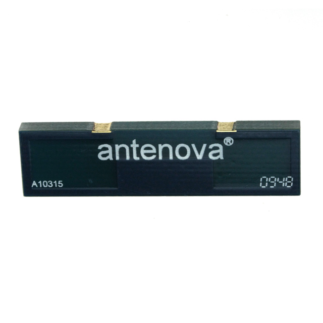
The Antenova A10315 is a PCB trace RF antenna designed for cellular applications operating across 850MHz, 900MHz, 1.8GHz, and 1.9GHz frequency bands. This component is part of the Reflexus series and is classified as obsolete. Due to its obsolete status, identifying equivalent substitute parts with compatible electrical and mechanical characteristics is essential for ongoing system support and new design implementations requiring similar performance parameters.
Substiute Parts
Key Parameters
| Parameter | Value |
|---|---|
| Manufacturer Part Number | A10315 |
| Manufacturer | Antenova |
| Antenna Type | PCB Trace |
| Frequency Range | 824MHz ~ 960MHz, 1.71GHz ~ 2.17GHz |
| Number of Bands | 5 |
| Gain | 2dBi, 3.7dBi |
| VSWR | 2.3 |
| Return Loss | -8dB |
| Mounting Type | Surface Mount |
| Height (Max) | 0.126" (3.20mm) |
| Termination | Solder |
| Product Status | Obsolete |
| RoHS Status | RoHS Compliant |
| MSL Rating | 1 (Unlimited) |
Substitute Part Grouping Explanation
Substitution eligibility for the A10315 is determined by the following critical parameters:
Frequency Coverage: Substitute parts must support the core frequency bands of 824MHz ~ 960MHz and 1.71GHz ~ 2.17GHz to maintain GSM and UMTS compatibility.
Antenna Type: While the A10315 uses PCB trace technology, substitute parts may employ chip antenna designs provided they meet frequency and gain requirements within the specified ranges.
Mounting and Termination: All substitutes must use surface mount technology with solder termination to ensure PCB assembly compatibility.
Electrical Performance: VSWR and return loss values must remain within acceptable ranges for the target application. Gain values must fall within or exceed the specified performance envelope.
Compliance and Environmental: RoHS compliance and MSL ratings ensure regulatory and manufacturing process compatibility.
The two identified substitute parts—Taoglas PA.700.J and Taoglas PCS.06.A—meet these substitution criteria through overlapping frequency coverage, compatible mounting methods, and equivalent electrical performance characteristics.
Parameter Comparison
| Parameter | A10315 (Antenova) | PA.700.J (Taoglas) | PCS.06.A (Taoglas) |
|---|---|---|---|
| Antenna Type | PCB Trace | Chip | Chip |
| Frequency Range | 824MHz ~ 960MHz, 1.71GHz ~ 2.17GHz | 698MHz ~ 800MHz, 824MHz ~ 960MHz, 1.41GHz ~ 1.52GHz, 1.71GHz ~ 2.17GHz, 2.4GHz ~ 2.7GHz | 698MHz ~ 960MHz, 1.71GHz ~ 2.69GHz |
| Number of Bands | 5 | 6 | 7 |
| Gain Range | 2dBi, 3.7dBi | -3.6dBi to 2.7dBi | -0.21dBi to 3.72dBi |
| VSWR | 2.3 | 4.6 | Not specified |
| Return Loss | -8dB | -5dB to -14dB | -7dB, -6dB |
| Mounting Type | Surface Mount | Surface Mount | Surface Mount |
| Height (Max) | 0.126" (3.20mm) | 0.197" (5.00mm) | 0.118" (3.00mm) |
| Termination | Solder | Solder | Solder |
| Packaging | Tape & Reel (TR) | Cut Tape (CT) | Tape & Reel (TR) |
| Product Status | Obsolete | Active | Active |
| RoHS Status | RoHS Compliant | ROHS3 Compliant | ROHS3 Compliant |
| MSL Rating | 1 (Unlimited) | 3 (168 Hours) | 3 (168 Hours) |
Engineering Selection Recommendations
PA.700.J Selection: This substitute provides extended frequency coverage including 698MHz ~ 800MHz and 2.4GHz ~ 2.7GHz bands beyond the A10315 specification. The part is active and ROHS3 compliant. The increased height of 0.197" (5.00mm) versus 0.126" (3.20mm) requires PCB layout verification. VSWR of 4.6 is higher than the original 2.3, indicating slightly reduced impedance matching efficiency. Return loss values ranging from -5dB to -14dB provide variable performance across frequency bands. Cut tape packaging differs from the original tape & reel format.
PCS.06.A Selection: This substitute offers the broadest frequency coverage (698MHz ~ 960MHz, 1.71GHz ~ 2.69GHz) with seven supported bands. The part is active and ROHS3 compliant. Height of 0.118" (3.00mm) is compatible with the original 3.20mm specification, minimizing PCB redesign requirements. Gain values range from -0.21dBi to 3.72dBi, encompassing the original performance envelope. Tape & reel packaging matches the original format. Return loss specifications of -7dB and -6dB are within acceptable ranges.
Both substitutes are manufactured by Taoglas Limited and maintain active product status, ensuring long-term availability and supply chain stability compared to the obsolete A10315.
Frequently Asked Questions (FAQ)
Q: Can the PA.700.J or PCS.06.A be used as direct drop-in replacements for the A10315?
A: Both parts are surface mount solder-terminated antennas with compatible frequency coverage for GSM and UMTS applications. However, physical dimensions differ. The PCS.06.A height of 3.00mm is closer to the original 3.20mm, while PA.700.J at 5.00mm may require PCB layout modifications. Electrical performance characteristics vary, particularly VSWR and return loss values, requiring impedance matching circuit validation.
Q: What is the significance of the antenna type change from PCB trace to chip?
A: PCB trace antennas are implemented as printed patterns on the circuit board, while chip antennas are discrete components. Chip antennas offer improved performance consistency and reduced design complexity but require dedicated PCB footprints. Both mounting approaches are surface mount compatible and solder-terminated.
Q: How do the MSL ratings affect component handling?
A: The A10315 carries MSL 1 (unlimited shelf life), while both substitutes carry MSL 3 (168-hour floor life after moisture exposure). MSL 3 components require stricter moisture control during storage and assembly. Baking procedures may be necessary if floor life is exceeded before reflow soldering.
Q: Why does PA.700.J have higher VSWR than the A10315?
A: VSWR of 4.6 versus 2.3 indicates less efficient impedance matching at certain frequencies. This affects signal reflection and antenna efficiency. Circuit design validation is required to confirm acceptable performance in the target application.
Q: Are there packaging format considerations for production?
A: The A10315 and PCS.06.A use tape & reel (TR) packaging suitable for automated assembly. The PA.700.J uses cut tape (CT) packaging, which may require manual handling or different feeder compatibility depending on assembly equipment.
Q: Do both substitutes support the full frequency range of the A10315?
A: Yes. Both PA.700.J and PCS.06.A cover the required 824MHz ~ 960MHz and 1.71GHz ~ 2.17GHz ranges. Both also provide extended coverage beyond the original specification, supporting additional cellular standards and frequency bands.
Alternative Parts

SJ6012L2TP
Littelfuse Inc.
6 Alternative Parts

JMK107BBJ476MA-RE
Taiyo Yuden
10 Alternative Parts

GMK107BBJ475MA-T
Taiyo Yuden
5 Alternative Parts
SJ6020N2ARP
Littelfuse Inc.
3 Alternative Parts
SJ6025R2ATP
Littelfuse Inc.
4 Alternative Parts

2474-05L
API Delevan Inc.
1 Alternative Parts

4590R-684K
API Delevan Inc.
1 Alternative Parts

CM6560R-334
API Delevan Inc.
1 Alternative Parts

CM6460-104
API Delevan Inc.
1 Alternative Parts

5526-12
API Delevan Inc.
1 Alternative Parts