


Request Quote
(Ships tomorrow)
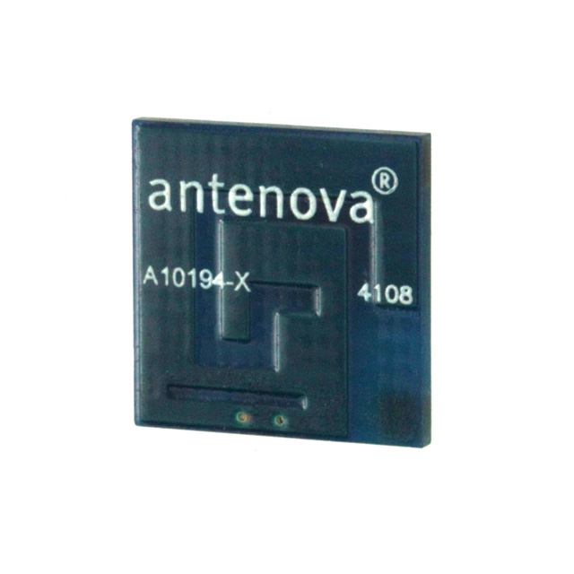
Antenova A10194 RF Antenna Equivalent & Substitute Parts
Part Overview
The Antenova A10194 is a dual-band PCB trace RF antenna designed for WLAN applications operating at 2.4GHz and 5GHz frequency bands. This component is classified as obsolete, making equivalent and substitute parts necessary for new designs and ongoing production requirements. The A10194 provides 1.8dBi and 4.1dBi gain across its operating bands with solder surface mount termination.
Substiute Parts
Key Parameters
| Parameter | Value |
|---|---|
| Manufacturer Part Number | A10194 |
| Manufacturer | Antenova |
| RF Family/Standard | WiFi |
| Frequency (Center/Band) | 2.4GHz, 5GHz |
| Frequency Range | 2.4GHz ~ 2.5GHz, 4.9GHz ~ 5GHz |
| Antenna Type | PCB Trace |
| Number of Bands | 2 |
| Gain | 1.8dBi, 4.1dBi |
| VSWR | 1.4, 1.8 |
| Return Loss | -11dB, -15dB |
| Termination | Solder |
| Mounting Type | Surface Mount |
| Height (Max) | 0.035" (0.90mm) |
| Product Status | Obsolete |
| RoHS Status | RoHS Compliant |
| MSL | 1 (Unlimited) |
Substitute Part Grouping Explanation
Substitution for the A10194 is determined by the following critical parameters:
- RF Family/Standard: WiFi applications only
- Frequency Coverage: Dual-band operation at 2.4GHz and 5GHz bands
- Antenna Type: PCB trace or equivalent low-profile antenna technology
- Termination Method: Solder surface mount
- Mounting Type: Surface mount configuration
- Gain Performance: Minimum 1.8dBi at 2.4GHz and 4.1dBi at 5GHz
- VSWR and Return Loss: Impedance matching within specified ranges
- Physical Height: Maximum 0.90mm to maintain PCB integration compatibility
Among the provided substitute parts, only the WDP.2458.25.4.B.02 from Taoglas Limited meets the core substitution criteria for WiFi dual-band antenna applications. This part operates across the same 2.4GHz and 5GHz frequency bands required for WLAN systems.
The PCS.07.A and SGGP.25.4.A.02 are not suitable substitutes due to fundamental application mismatches: PCS.07.A is designed for cellular bands (850MHz–2.17GHz), and SGGP.25.4.A.02 is designed for navigation systems (GPS/GLONASS at 1.575–1.602GHz).
Parameter Comparison
| Parameter | A10194 (Antenova) | WDP.2458.25.4.B.02 (Taoglas) |
|---|---|---|
| RF Family/Standard | WiFi | WiFi |
| Frequency (Center/Band) | 2.4GHz, 5GHz | 2.4GHz, 5.5GHz |
| Frequency Range | 2.4GHz ~ 2.5GHz, 4.9GHz ~ 5GHz | 2.4GHz ~ 2.5GHz, 5.15GHz ~ 5.85GHz |
| Antenna Type | PCB Trace | Ceramic Patch |
| Number of Bands | 2 | 2 |
| Gain | 1.8dBi, 4.1dBi | 6dBi, 8dBi |
| Return Loss | -11dB, -15dB | -19dB, -5dB |
| Termination | Solder | Pin |
| Mounting Type | Surface Mount | Surface Mount |
| Height (Max) | 0.035" (0.90mm) | 0.157" (4.00mm) |
| Product Status | Obsolete | Active |
| RoHS Status | RoHS Compliant | ROHS3 Compliant |
| MSL | 1 (Unlimited) | 1 (Unlimited) |
Engineering Selection Recommendations
The WDP.2458.25.4.B.02 is the only viable substitute among the provided parts for WiFi WLAN applications. Selection considerations based on provided specifications:
Frequency Coverage: The WDP.2458.25.4.B.02 covers the required 2.4GHz band fully (2.4–2.5GHz) and extends the 5GHz coverage to 5.15–5.85GHz, which encompasses the A10194's 4.9–5GHz range.
Gain Performance: The WDP.2458.25.4.B.02 provides higher gain (6dBi and 8dBi) compared to the A10194 (1.8dBi and 4.1dBi). This increased gain may require circuit-level adjustments in receiver sensitivity or transmit power settings.
Antenna Type and Physical Profile: The WDP.2458.25.4.B.02 uses ceramic patch technology with a maximum height of 4.00mm, compared to the A10194's PCB trace design at 0.90mm. PCB layout modifications are necessary to accommodate the increased height.
Termination Method: The WDP.2458.25.4.B.02 uses pin termination, whereas the A10194 uses solder termination. This requires changes to the PCB footprint and assembly process.
Compliance: Both parts are RoHS compliant. The WDP.2458.25.4.B.02 meets ROHS3 standards and maintains MSL 1 rating, ensuring compatibility with standard manufacturing processes.
Product Status: The WDP.2458.25.4.B.02 is active, ensuring long-term availability and supply chain stability.
Frequently Asked Questions (FAQ)
Q: Can the PCS.07.A or SGGP.25.4.A.02 be used as substitutes for the A10194?
A: No. The PCS.07.A is designed for cellular applications (850MHz–2.17GHz) and does not cover WiFi bands. The SGGP.25.4.A.02 is designed for GPS/GLONASS navigation (1.575–1.602GHz) and is not suitable for WLAN applications.
Q: What are the main differences between the A10194 and WDP.2458.25.4.B.02?
A: The primary differences are antenna type (PCB trace vs. ceramic patch), physical height (0.90mm vs. 4.00mm), termination method (solder vs. pin), and gain performance (1.8/4.1dBi vs. 6/8dBi). Frequency coverage is compatible for WiFi applications.
Q: Does the higher gain of the WDP.2458.25.4.B.02 affect system performance?
A: The higher gain may require adjustment of receiver sensitivity or transmit power levels in the RF circuit design. Impedance matching and return loss characteristics should be verified during integration.
Q: Are there packaging differences between the A10194 and WDP.2458.25.4.B.02?
A: Yes. The A10194 is supplied in Cut Tape (CT) packaging, while the WDP.2458.25.4.B.02 is supplied in Tray packaging. Assembly processes may require adjustment accordingly.
Q: What PCB modifications are required to use the WDP.2458.25.4.B.02?
A: The footprint must be redesigned to accommodate pin termination instead of solder termination. The increased height (4.00mm vs. 0.90mm) requires verification of clearance in the PCB assembly area.
Q: Are both parts RoHS compliant?
A: Yes. The A10194 is RoHS Compliant, and the WDP.2458.25.4.B.02 is ROHS3 Compliant. Both meet environmental compliance requirements.
Alternative Parts

SJ6012L2TP
Littelfuse Inc.
6 Alternative Parts

JMK107BBJ476MA-RE
Taiyo Yuden
10 Alternative Parts

GMK107BBJ475MA-T
Taiyo Yuden
5 Alternative Parts
SJ6020N2ARP
Littelfuse Inc.
3 Alternative Parts
SJ6025R2ATP
Littelfuse Inc.
4 Alternative Parts

2474-05L
API Delevan Inc.
1 Alternative Parts

4590R-684K
API Delevan Inc.
1 Alternative Parts

CM6560R-334
API Delevan Inc.
1 Alternative Parts

CM6460-104
API Delevan Inc.
1 Alternative Parts

5526-12
API Delevan Inc.
1 Alternative Parts