


Request Quote
(Ships tomorrow)
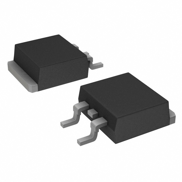
IRF1010 N-Channel 55V 85A MOSFET D2PAK Equivalent & Substitute Parts
Part Overview
The IRF1010 (Infineon Technologies, part number 94-4796) is an N-Channel MOSFET in D2PAK surface mount packaging, rated for 55V drain-to-source voltage and 85A continuous drain current at 25°C. This device belongs to the HEXFET® series and is classified as obsolete. Due to its obsolete status, equivalent and substitute parts from active product lines are necessary to maintain design continuity and ensure long-term component availability for new production and field replacements.
Substiute Parts
Key Parameters
| Parameter | Value | Unit |
|---|---|---|
| Drain-to-Source Voltage (Vdss) | 55 | V |
| Continuous Drain Current @ 25°C (Id) | 85 | A (Tc) |
| On-State Resistance @ 43A, 10V (Rds On Max) | 11 | mOhm |
| Gate-Source Threshold Voltage @ 250µA (Vgs th Max) | 4 | V |
| Gate Charge @ 10V (Qg Max) | 120 | nC |
| Input Capacitance @ 25V (Ciss Max) | 3210 | pF |
| Power Dissipation (Max) | 180 | W (Tc) |
| Operating Temperature Range | -55 to 175 | °C (TJ) |
| Package Type | D2PAK (TO-263-3) | Surface Mount |
| FET Type | N-Channel | — |
| Technology | MOSFET (Metal Oxide) | — |
Substitute Part Grouping Explanation
Substitution of the IRF1010 is determined by the following critical electrical and mechanical parameters:
Primary Substitution Criteria:
- Drain-to-Source Voltage (Vdss): Must equal or exceed 55V
- Continuous Drain Current (Id): Must equal or exceed 85A at 25°C
- On-State Resistance (Rds On): Must not significantly exceed 11 mOhm to maintain thermal performance
- Package Type: Must be D2PAK (TO-263-3) surface mount
- Operating Temperature Range: Must support -55°C to 175°C
Secondary Compatibility Factors:
- Gate Charge (Qg): Lower values reduce switching losses
- Input Capacitance (Ciss): Lower values improve switching speed
- Power Dissipation Rating: Must support thermal requirements of the application
- RoHS Compliance: Active substitutes must meet ROHS3 compliance
Substitute parts are grouped into three categories based on electrical performance alignment:
Category 1 – Direct Voltage/Current Match (55V, 75–85A): Parts with 55V Vdss and drain current within 75–85A range, maintaining similar Rds On characteristics. These include BUK9612-55B,118 and BUK7610-55AL,118.
Category 2 – Higher Voltage Rating (60–80V, 50–100A): Parts with elevated Vdss (60V–80V) and comparable or higher drain current ratings. These provide enhanced voltage margin and are suitable when circuit design permits higher voltage ratings. Examples include HUF75545S3ST, STB140NF55T4, and PSMN7R6-60BS,118.
Category 3 – Lower Current Capability (50A at elevated voltage): Parts with reduced drain current but higher voltage ratings or improved efficiency characteristics. These are applicable only when circuit current requirements can be met at the lower rating. Examples include IPB090N06N3GATMA1 and PSMN015-60BS,118.
All substitute parts maintain D2PAK packaging, surface mount configuration, and compatible gate drive voltage specifications (±15V to ±20V Vgs Max).
Parameter Comparison
| Parameter | IRF1010 (Main) | BUK9612-55B,118 | HUF75545S3ST | STB140NF55T4 | PSMN7R6-60BS,118 | BUK7610-55AL,118 |
|---|---|---|---|---|---|---|
| Vdss (V) | 55 | 55 | 80 | 55 | 60 | 55 |
| Id @ 25°C (A Tc) | 85 | 75 | 75 | 80 | 92 | 75 |
| Rds On Max (mOhm) | 11 @ 43A, 10V | 10 @ 25A, 10V | 10 @ 75A, 10V | 8 @ 40A, 10V | 7.8 @ 25A, 10V | 10 @ 25A, 10V |
| Vgs th Max (V) | 4 @ 250µA | 2 @ 1mA | 4 @ 250µA | 4 @ 250µA | 4 @ 1mA | 4 @ 1mA |
| Qg Max (nC) | 120 @ 10V | 31 @ 5V | 235 @ 20V | 142 @ 10V | 38.7 @ 10V | 124 @ 10V |
| Ciss Max (pF) | 3210 @ 25V | 3693 @ 25V | 3750 @ 25V | 5300 @ 25V | 2651 @ 30V | 6280 @ 25V |
| Power Dissipation Max (W Tc) | 180 | 157 | 270 | 300 | 149 | 300 |
| Operating Temp Range (°C TJ) | -55 to 175 | -55 to 175 | -55 to 175 | -55 to 175 | -55 to 175 | -55 to 175 |
| Package | D2PAK | D2PAK | D2PAK | D2PAK | D2PAK | D2PAK |
| Product Status | Obsolete | Active | Active | Active | Active | Obsolete |
| RoHS Status | Non-compliant | ROHS3 Compliant | ROHS3 Compliant | ROHS3 Compliant | ROHS3 Compliant | ROHS3 Compliant |
Engineering Selection Recommendations
Primary Recommendation – BUK9612-55B,118 (Nexperia USA Inc.)
BUK9612-55B,118 is the preferred substitute for the IRF1010. This part maintains identical 55V Vdss rating and 75A continuous drain current, providing direct functional equivalence within 88% of the original current specification. The device features improved on-state resistance (10 mOhm vs. 11 mOhm) and significantly reduced gate charge (31 nC vs. 120 nC), resulting in lower switching losses and improved thermal efficiency. BUK9612-55B,118 is ROHS3 compliant, AEC-Q101 automotive qualified, and carries active product status with extensive inventory availability (500,400 pcs). The TrenchMOS™ technology provides superior performance characteristics compared to the obsolete HEXFET® series.
Secondary Recommendation – STB140NF55T4 (STMicroelectronics)
STB140NF55T4 offers 55V Vdss with 80A continuous drain current (94% of IRF1010 rating) and superior on-state resistance (8 mOhm). This STripFET™ II device provides enhanced thermal performance with 300W power dissipation rating and is ROHS3 compliant with active product status. Gate charge of 142 nC is moderately higher than BUK9612-55B,118 but acceptable for most switching applications. Inventory availability is substantial (15,365 pcs).
Alternative for Higher Current Margin – PSMN7R6-60BS,118 (Nexperia USA Inc.)
PSMN7R6-60BS,118 provides 60V Vdss with 92A continuous drain current, exceeding the IRF1010 specification by 8%. This part delivers the lowest on-state resistance (7.8 mOhm) among active substitutes and reduced gate charge (38.7 nC), making it suitable for applications requiring maximum efficiency. The 60V rating provides additional voltage margin for transient protection. ROHS3 compliant and actively produced (8,822 pcs available).
Higher Voltage Alternative – HUF75545S3ST (onsemi)
HUF75545S3ST is rated for 80V Vdss with 75A continuous drain current. This UltraFET™ device is appropriate for designs where elevated voltage margin is required or where circuit topology permits higher voltage operation. On-state resistance of 10 mOhm matches the IRF1010 specification. ROHS3 compliant with active status (4,600 pcs available).
Selection Criteria Summary:
- For direct replacement with improved efficiency: BUK9612-55B,118
- For maximum thermal performance: STB140NF55T4
- For highest current capability: PSMN7R6-60BS,118
- For elevated voltage margin: HUF75545S3ST
All recommended substitutes are ROHS3 compliant, actively manufactured, and available in D2PAK packaging. The IRF1010's obsolete status and RoHS non-compliance make transition to active alternatives necessary for new designs and long-term production support.
Frequently Asked Questions (FAQ)
Q1: Can BUK9612-55B,118 directly replace IRF1010 in existing PCB layouts?
Yes. Both devices use identical D2PAK (TO-263-3) surface mount packaging with the same pin configuration (Gate, Drain, Source). No PCB modification is required. Gate drive voltage compatibility is maintained (±15V Vgs Max for BUK9612-55B,118 vs. ±20V for IRF1010), ensuring compatibility with existing gate drive circuits.
Q2: What is the current derating when substituting with BUK9612-55B,118?
BUK9612-55B,118 is rated for 75A continuous drain current versus IRF1010's 85A, representing a 12% reduction in maximum current capability. For applications operating at or near 85A, thermal analysis is required to confirm the substitute can dissipate the equivalent power. The improved Rds On (10 mOhm vs. 11 mOhm) partially offsets this derating through reduced conduction losses.
Q3: Are there thermal performance differences between IRF1010 and recommended substitutes?
Yes. BUK9612-55B,118 has lower power dissipation rating (157W vs. 180W) but superior on-state resistance and significantly reduced gate charge, resulting in lower switching losses. STB140NF55T4 offers higher power dissipation rating (300W) and lower Rds On (8 mOhm), providing superior thermal performance. PSMN7R6-60BS,118 combines the lowest Rds On (7.8 mOhm) with 60V rating, optimizing efficiency. Thermal design must account for these differences.
Q4: What is the impact of reduced gate charge on circuit design?
Reduced gate charge (31 nC for BUK9612-55B,118 vs. 120 nC for IRF1010) decreases gate drive power requirements and enables faster switching transitions. This reduces switching losses and improves efficiency, particularly in high-frequency applications. Existing gate drive circuits designed for IRF1010 will operate reliably with lower gate charge devices; no circuit modification is necessary.
Q5: Can PSMN7R6-60BS,118 be used in 55V-rated circuits?
Yes. PSMN7R6-60BS,118 is rated for 60V Vdss, which exceeds the 55V circuit requirement. The additional 5V voltage margin provides protection against transient overvoltages and improves reliability. No circuit modification is required; the device operates safely within the 55V design envelope.
Q6: What is the significance of RoHS3 compliance for substitute selection?
RoHS3 compliance is mandatory for new product designs and production in most markets. The IRF1010 is RoHS non-compliant (obsolete technology). All recommended substitutes are ROHS3 compliant, ensuring regulatory compliance for new manufacturing and future product certifications. This is a critical factor for long-term design viability.
Q7: Are automotive-grade alternatives available?
Yes. BUK9612-55B,118 and BUK7610-55AL,118 are both AEC-Q101 automotive qualified. These devices are suitable for automotive applications requiring automotive-grade component certification. Non-automotive substitutes (HUF75545S3ST, STB140NF55T4, PSMN7R6-60BS,118) are not automotive qualified and must not be used in automotive designs requiring AEC-Q101 certification.
Q8: How do input capacitance differences affect circuit performance?
Input capacitance (Ciss) ranges from 2,651 pF (PSMN7R6-60BS,118) to 6,280 pF (BUK7610-55AL,118) among substitutes, compared to 3,210 pF for IRF1010. Lower Ciss reduces gate drive current requirements and improves switching speed. Higher Ciss increases gate drive power but does not prevent substitution. Gate drive circuit design must accommodate the Ciss value of the selected substitute.
Q9: What inventory considerations apply to substitute selection?
BUK9612-55B,118 has the highest inventory availability (500,400 pcs), ensuring long-term supply security. STB140NF55T4 (15,365 pcs) and PSMN015-60BS,118 (12,675 pcs) also provide substantial availability. Inventory levels support both immediate replacement needs and long-term production requirements. Verify current inventory status with suppliers before final design commitment.
Q10: Is thermal interface material (TIM) application different for substitute parts?
No. All substitute parts use identical D2PAK packaging with the same thermal tab configuration as IRF1010. Thermal interface material application procedures, mounting hardware, and heatsink compatibility remain unchanged. Thermal performance differences result from electrical characteristics (Rds On, gate charge), not packaging differences.
Alternative Parts

SJ6012L2TP
Littelfuse Inc.
6 Alternative Parts

JMK107BBJ476MA-RE
Taiyo Yuden
10 Alternative Parts

GMK107BBJ475MA-T
Taiyo Yuden
5 Alternative Parts
SJ6020N2ARP
Littelfuse Inc.
3 Alternative Parts
SJ6025R2ATP
Littelfuse Inc.
4 Alternative Parts

2474-05L
API Delevan Inc.
1 Alternative Parts

4590R-684K
API Delevan Inc.
1 Alternative Parts

CM6560R-334
API Delevan Inc.
1 Alternative Parts

CM6460-104
API Delevan Inc.
1 Alternative Parts

5526-12
API Delevan Inc.
1 Alternative Parts