


Request Quote
(Ships tomorrow)
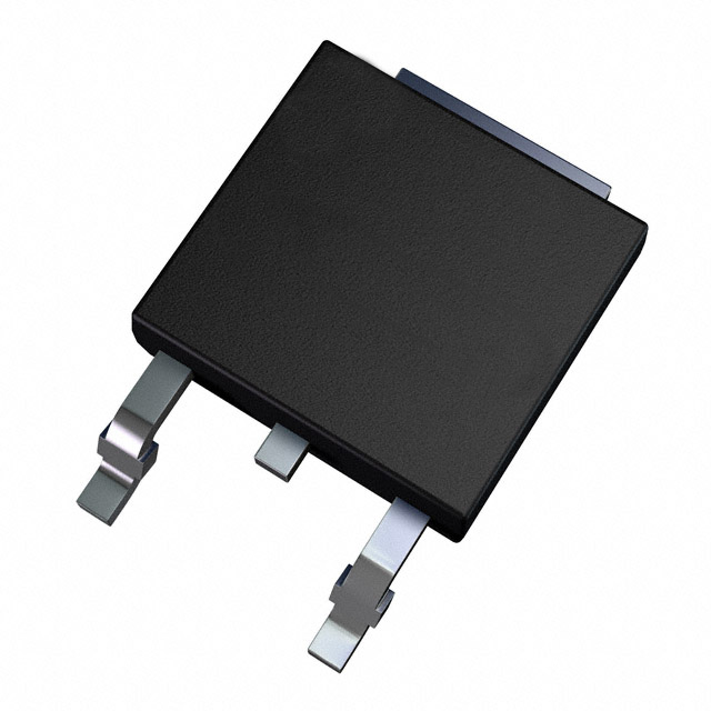
IRFR4105 N-Channel MOSFET 55V 27A DPAK Equivalent & Substitute Parts
Part Overview
The Infineon IRFR4105 is an N-Channel MOSFET rated for 55V drain-to-source voltage with 27A continuous drain current in a TO-252AA (DPAK) surface mount package. This device is classified as obsolete, necessitating identification of active equivalent and substitute components for new designs and production continuity. The IRFR4105 operates across the temperature range of -55°C to 175°C and dissipates up to 68W at the case temperature. Substitute parts must maintain electrical compatibility within the specified voltage, current, and thermal parameters while meeting modern RoHS compliance requirements.
Substiute Parts
Key Parameters
| Parameter | Value | Unit |
|---|---|---|
| Drain-to-Source Voltage (Vdss) | 55 | V |
| Continuous Drain Current (Id) @ 25°C | 27 | A |
| On-State Resistance (Rds On) @ 16A, 10V | 45 | mOhm |
| Gate Threshold Voltage (Vgs(th)) @ 250µA | 4 | V |
| Gate Charge (Qg) @ 10V | 34 | nC |
| Input Capacitance (Ciss) @ 25V | 700 | pF |
| Power Dissipation (Max) | 68 | W |
| Operating Temperature Range | -55 to 175 | °C |
| Package Type | TO-252-3 (DPAK) | — |
| Mounting Type | Surface Mount | — |
Substitute Part Grouping Explanation
Substitution of the IRFR4105 is determined by electrical and mechanical compatibility across the following critical parameters:
Voltage Rating Compatibility: Substitute parts must support a minimum Vdss of 55V. Parts rated at 60V, 100V, or higher are electrically compatible for applications requiring 55V operation.
Current Rating Compatibility: The continuous drain current (Id) must equal or exceed 27A at 25°C. Substitute parts rated at 23A or higher satisfy this requirement, though higher ratings provide additional design margin.
On-State Resistance (Rds On): The reference device specifies 45mOhm maximum at 16A and 10V gate drive. Substitute parts with equal or lower Rds On values maintain or improve switching efficiency and thermal performance.
Gate Drive Voltage: The IRFR4105 operates with 10V gate drive. Substitute parts specified for 10V drive voltage or dual-rated (4.5V/10V or 5V/10V) are compatible.
Package and Mounting: All substitutes must use TO-252-3 (DPAK) surface mount packaging to ensure mechanical and thermal interface compatibility.
Temperature Range: Operating temperature range of -55°C to 175°C must be maintained across all substitute selections.
Compliance Status: The obsolete IRFR4105 (RoHS non-compliant) should be replaced with RoHS3-compliant active parts for new designs and production.
Parameter Comparison
| Part Number | Manufacturer | Vdss (V) | Id @ 25°C (A) | Rds On (mOhm) | Vgs(th) (V) | Qg (nC) | Ciss (pF) | Pd Max (W) | Status | RoHS |
|---|---|---|---|---|---|---|---|---|---|---|
| IRFR4105 | Infineon | 55 | 27 | 45 @ 16A, 10V | 4 @ 250µA | 34 @ 10V | 700 @ 25V | 68 | Obsolete | Non-compliant |
| IRFR4105TRPBF | Infineon | 55 | 27 | 45 @ 16A, 10V | 4 @ 250µA | 34 @ 10V | 700 @ 25V | 68 | Active | RoHS3 |
| IPD30N10S3L34ATMA1 | Infineon | 100 | 30 | 31 @ 30A, 10V | 2.4 @ 29µA | 31 @ 10V | 1976 @ 25V | 57 | Active | RoHS3 |
| STD15NF10T4 | STMicroelectronics | 100 | 23 | 65 @ 12A, 10V | 4 @ 250µA | 40 @ 10V | 870 @ 25V | 70 | Active | RoHS3 |
| STD16NF06T4 | STMicroelectronics | 60 | 16 | 70 @ 8A, 10V | 2 @ 250µA | 14.1 @ 10V | 400 @ 15V | 40 | Active | RoHS3 |
| STD20NF06LT4 | STMicroelectronics | 60 | 24 | 40 @ 12A, 10V | 2.5 @ 250µA | 13 @ 10V | 660 @ 25V | 60 | Active | RoHS3 |
| STD20NF06T4 | STMicroelectronics | 60 | 24 | 40 @ 12A, 10V | 4 @ 250µA | 31 @ 10V | 690 @ 25V | 60 | Active | RoHS3 |
| STD25NF10LT4 | STMicroelectronics | 100 | 25 | 35 @ 12.5A, 10V | 2.5 @ 250µA | 52 @ 5V | 1710 @ 25V | 100 | Active | RoHS3 |
| STD25NF10T4 | STMicroelectronics | 100 | 25 | 38 @ 12.5A, 10V | 4 @ 250µA | 55 @ 10V | 1550 @ 25V | 100 | Active | RoHS3 |
| STD26NF10 | STMicroelectronics | 100 | 25 | 38 @ 12.5A, 10V | 4 @ 250µA | 55 @ 10V | 1550 @ 25V | 100 | Active | RoHS3 |
| STD35NF06T4 | STMicroelectronics | 60 | 35 | 20 @ 17.5A, 10V | 4 @ 250µA | 60 @ 10V | 1300 @ 25V | 80 | Active | RoHS3 |
Engineering Selection Recommendations
Direct Replacement (Identical Electrical Specifications):
IRFR4105TRPBF is the active production equivalent of the obsolete IRFR4105. This part maintains identical electrical parameters (55V, 27A, 45mOhm Rds On, 68W power dissipation) and package configuration. The primary distinction is RoHS3 compliance and active product status. This part is the preferred selection for direct substitution in existing designs.
Higher Voltage Rating Substitutes (100V Rated):
IPD30N10S3L34ATMA1, STD25NF10LT4, STD25NF10T4, and STD26NF10 are rated for 100V operation, providing enhanced voltage margin for 55V applications. These parts maintain or exceed the 27A current requirement and offer improved on-state resistance characteristics. The 100V rating ensures compatibility with transient overvoltage conditions while maintaining thermal performance. All are RoHS3 compliant and active.
60V Rated Substitutes:
STD20NF06LT4 and STD20NF06T4 are rated for 60V with 24A continuous current, providing minimal voltage margin above the 55V requirement. These parts offer comparable on-state resistance (40mOhm) and are suitable for applications with controlled voltage stress. STD35NF06T4 provides 35A current capability at 60V with superior on-state resistance (20mOhm), enabling thermal performance improvement in current-limited applications.
Lower Current Rating Consideration:
STD15NF10T4 and STD16NF06T4 are rated below the 27A requirement and are not recommended for direct replacement in applications requiring full 27A continuous current. These parts are suitable only for applications with reduced current demands.
Compliance and Inventory:
All recommended substitutes carry RoHS3 compliance certification and active product status, ensuring long-term availability and regulatory compliance for new production. Inventory levels vary significantly; STD25NF10T4 and STD25NF10LT4 maintain the highest stock levels, supporting high-volume production requirements.
Frequently Asked Questions (FAQ)
Q: Can IRFR4105TRPBF be used as a direct replacement for the obsolete IRFR4105?
A: Yes. IRFR4105TRPBF is the active production equivalent with identical electrical specifications and package configuration. The only substantive difference is RoHS3 compliance status. This is the recommended direct replacement.
Q: What is the primary advantage of selecting a 100V-rated substitute over the 55V-rated IRFR4105TRPBF?
A: 100V-rated devices provide enhanced voltage margin for transient overvoltage protection while maintaining or improving on-state resistance and thermal performance. In applications subject to voltage spikes or switching transients, the higher voltage rating reduces stress on the device and extends operational life.
Q: Are STD20NF06LT4 and STD20NF06T4 interchangeable?
A: Both parts are rated for 60V and 24A with identical on-state resistance (40mOhm @ 12A, 10V). The primary difference is gate threshold voltage: STD20NF06LT4 specifies 2.5V while STD20NF06T4 specifies 4V. Selection depends on gate drive circuit design and switching speed requirements.
Q: Why is STD15NF10T4 not recommended as a substitute?
A: STD15NF10T4 is rated for 23A continuous current, which is below the IRFR4105 specification of 27A. This part is unsuitable for applications requiring full 27A operation and would result in thermal stress and potential device failure.
Q: Do all substitute parts use the same TO-252-3 (DPAK) package?
A: Yes. All substitute parts listed use TO-252-3 (DPAK) surface mount packaging, ensuring mechanical and thermal interface compatibility with existing PCB layouts and thermal management designs.
Q: What is the significance of gate charge (Qg) differences between substitute parts?
A: Gate charge affects switching speed and gate drive circuit power consumption. Lower gate charge (31-34 nC) enables faster switching and reduced driver power dissipation. Higher gate charge (40-60 nC) may require higher gate drive current but does not affect DC electrical compatibility.
Q: Are there performance differences between STD25NF10LT4 and STD25NF10T4?
A: Both parts are rated for 100V and 25A with similar on-state resistance (35-38 mOhm). STD25NF10LT4 specifies lower gate threshold voltage (2.5V) and lower gate charge (52 nC @ 5V), enabling faster switching response. STD25NF10T4 specifies 4V threshold and 55 nC gate charge @ 10V. Selection depends on gate drive voltage and switching frequency requirements.
Q: Can substitute parts with higher current ratings (e.g., STD35NF06T4 at 35A) be used in place of the 27A IRFR4105?
A: Yes. Higher current-rated devices are electrically compatible and provide additional design margin. The 35A rating of STD35NF06T4 does not create compatibility issues; the device will operate safely at 27A with improved thermal performance due to lower on-state resistance (20mOhm).
Q: What compliance certifications are required for new production designs?
A: All recommended substitute parts carry RoHS3 compliance certification. The obsolete IRFR4105 is RoHS non-compliant and should not be used in new designs subject to RoHS regulatory requirements.
Q: How does input capacitance (Ciss) variation affect circuit design?
A: Input capacitance affects gate drive circuit design and switching transient behavior. Substitute parts with higher Ciss values (1550-1976 pF) require higher gate drive current for equivalent switching speed compared to the reference device (700 pF). This parameter should be evaluated in high-frequency switching applications.
Alternative Parts

SJ6012L2TP
Littelfuse Inc.
6 Alternative Parts

JMK107BBJ476MA-RE
Taiyo Yuden
10 Alternative Parts

GMK107BBJ475MA-T
Taiyo Yuden
5 Alternative Parts
SJ6020N2ARP
Littelfuse Inc.
3 Alternative Parts
SJ6025R2ATP
Littelfuse Inc.
4 Alternative Parts

2474-05L
API Delevan Inc.
1 Alternative Parts

4590R-684K
API Delevan Inc.
1 Alternative Parts

CM6560R-334
API Delevan Inc.
1 Alternative Parts

CM6460-104
API Delevan Inc.
1 Alternative Parts

5526-12
API Delevan Inc.
1 Alternative Parts