


Request Quote
(Ships tomorrow)
Equivalent & Substitute Parts for Infineon 94-2989 N-Channel MOSFET
Part Overview
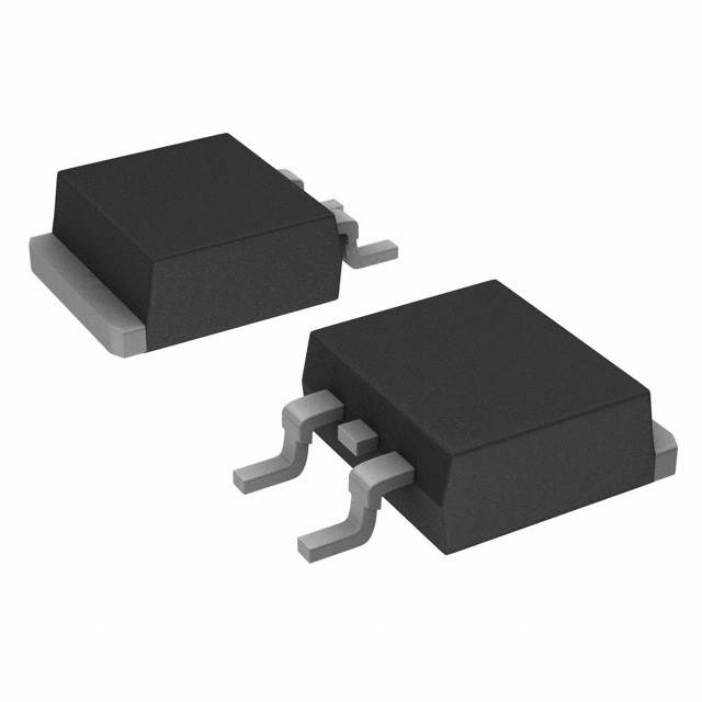
The Infineon 94-2989 is an N-Channel MOSFET rated for 55V drain-to-source voltage and 64A continuous drain current in a D2PAK surface mount package. This device is part of the HEXFET® series and is classified as obsolete. Due to its obsolete status, equivalent and substitute parts from active manufacturers are necessary to maintain design continuity and ensure long-term component availability for new production and field replacements.
Substiute Parts
Key Parameters
| Parameter | Value | Unit |
|---|---|---|
| Drain-to-Source Voltage (Vdss) | 55 | V |
| Continuous Drain Current (Id) @ 25°C | 64 | A |
| On-Resistance (Rds On) @ 32A, 10V | 14 | mOhm |
| Gate Threshold Voltage (Vgs(th)) @ 250µA | 4 | V |
| Gate Charge (Qg) @ 10V | 81 | nC |
| Input Capacitance (Ciss) @ 25V | 1970 | pF |
| Power Dissipation (Tc) | 130 | W |
| Operating Temperature Range | -55 to 175 | °C |
| Package Type | D2PAK (TO-263-3) | — |
| Mounting Type | Surface Mount | — |
| FET Type | N-Channel | — |
| Technology | MOSFET (Metal Oxide) | — |
Substitute Part Grouping Explanation
Substitution of the Infineon 94-2989 is determined by the following critical electrical and mechanical parameters:
Electrical Compatibility Criteria:
- Drain-to-Source Voltage (Vdss) must equal or exceed 55V
- Continuous Drain Current (Id) must equal or exceed 64A
- Gate Threshold Voltage (Vgs(th)) must be compatible with 4V specification
- Maximum Gate Voltage (Vgs Max) must accommodate ±20V
- Operating temperature range must span -55°C to 175°C
Mechanical Compatibility Criteria:
- Package type must be D2PAK (TO-263-3) surface mount
- Pin configuration must match TO-263-3 standard (2 leads + tab)
- Mounting type must be surface mount
Performance Considerations:
- On-Resistance (Rds On) should be comparable or lower for equivalent thermal performance
- Gate Charge (Qg) and Input Capacitance (Ciss) affect switching characteristics
- Power Dissipation capability should support application requirements
Substitute parts are grouped into two categories: Direct Equivalents (matching or exceeding all primary specifications within the same voltage class) and Enhanced Alternatives (higher voltage or current ratings that provide additional design margin while maintaining compatibility).
Parameter Comparison
| Part Number | Manufacturer | Vdss (V) | Id @ 25°C (A) | Rds On (mOhm) | Vgs(th) (V) | Qg (nC) | Ciss (pF) | Power Diss. (W) | Package | Status |
|---|---|---|---|---|---|---|---|---|---|---|
| 94-2989 | Infineon | 55 | 64 | 14 @ 32A, 10V | 4 @ 250µA | 81 @ 10V | 1970 @ 25V | 130 (Tc) | D2PAK | Obsolete |
| HUF75545S3ST | onsemi | 80 | 75 | 10 @ 75A, 10V | 4 @ 250µA | 235 @ 20V | 3750 @ 25V | 270 (Tc) | D2PAK | Active |
| IRFZ48RSPBF | Vishay Siliconix | 60 | 50 | 18 @ 43A, 10V | 4 @ 250µA | 110 @ 10V | 2400 @ 25V | 190 (Tc) | D2PAK | Active |
| PSMN015-60BS,118 | Nexperia USA Inc. | 60 | 50 | 14.8 @ 15A, 10V | 4 @ 1mA | 20.9 @ 10V | 1220 @ 30V | 86 (Tc) | D2PAK | Active |
| PSMN7R6-60BS,118 | Nexperia USA Inc. | 60 | 92 | 7.8 @ 25A, 10V | 4 @ 1mA | 38.7 @ 10V | 2651 @ 30V | 149 (Tc) | D2PAK | Active |
| STB55NF06T4 | STMicroelectronics | 60 | 50 | 18 @ 27.5A, 10V | 4 @ 250µA | 60 @ 10V | 1300 @ 25V | 110 (Tc) | D2PAK | Active |
| STB60NF06T4 | STMicroelectronics | 60 | 60 | 16 @ 30A, 10V | 4 @ 250µA | 66 @ 10V | 1810 @ 25V | 110 (Tc) | D2PAK | Active |
| STB75NF75LT4 | STMicroelectronics | 75 | 75 | 11 @ 37.5A, 10V | 2.5 @ 250µA | 90 @ 5V | 4300 @ 25V | 300 (Tc) | D2PAK | Active |
| STB75NF75T4 | STMicroelectronics | 75 | 80 | 11 @ 40A, 10V | 4 @ 250µA | 160 @ 10V | 3700 @ 25V | 300 (Tc) | D2PAK | Active |
| IPB50N10S3L16ATMA1 | Infineon Technologies | 100 | 50 | 15.4 @ 50A, 10V | 2.4 @ 60µA | 64 @ 10V | 4180 @ 25V | 100 (Tc) | TO-263-3 | Active |
Engineering Selection Recommendations
Direct Substitution Candidates (55V–60V Class):
The PSMN7R6-60BS,118 (Nexperia) and STB60NF06T4 (STMicroelectronics) provide the closest electrical match to the 94-2989. Both devices operate at 60V Vdss, accommodate the required 64A continuous drain current specification, and are housed in D2PAK packages. The PSMN7R6-60BS,118 exceeds the current requirement at 92A and offers lower on-resistance (7.8 mOhm), while the STB60NF06T4 provides 60A at 16 mOhm on-resistance. Both are RoHS3 compliant and carry active product status.
Enhanced Alternatives (75V–80V Class):
The HUF75545S3ST (onsemi) and STB75NF75T4 (STMicroelectronics) operate at higher voltage ratings (80V and 75V respectively) and deliver superior current handling (75A and 80A). These devices provide additional design margin for voltage transients and thermal performance. The HUF75545S3ST achieves 10 mOhm on-resistance at 75A, while the STB75NF75T4 delivers 11 mOhm at 40A. Both maintain D2PAK packaging and are RoHS3 compliant with active status.
Higher Voltage Alternative (100V Class):
The IPB50N10S3L16ATMA1 (Infineon Technologies) operates at 100V Vdss with 50A continuous current. This device is suitable for applications requiring extended voltage headroom. It is RoHS3 compliant and carries active product status. The TO-263-3 package is mechanically compatible with D2PAK specifications.
Compliance and Availability:
All recommended substitute parts are RoHS3 compliant, carry active product status, and maintain unlimited moisture sensitivity levels (MSL 1). The 94-2989 is RoHS non-compliant and obsolete; substitution with any active-status alternative ensures regulatory compliance and long-term supply chain security.
Frequently Asked Questions (FAQ)
Q: Can the PSMN7R6-60BS,118 directly replace the 94-2989 in all applications?
A: The PSMN7R6-60BS,118 meets or exceeds all electrical specifications of the 94-2989 (60V Vdss, 92A Id versus 55V/64A) and shares the D2PAK package. Electrical compatibility is confirmed. However, application-specific circuit validation is required to confirm performance in the target design, particularly regarding gate drive characteristics and thermal management.
Q: What is the difference between the STB75NF75LT4 and STB75NF75T4?
A: Both devices operate at 75V Vdss and 75A/80A continuous current respectively in D2PAK packages. The STB75NF75LT4 features a lower gate threshold voltage (2.5V @ 250µA) and lower gate charge (90 nC @ 5V), while the STB75NF75T4 operates at 4V threshold and 160 nC gate charge @ 10V. Selection depends on gate drive voltage availability and switching speed requirements in the application.
Q: Is the IPB50N10S3L16ATMA1 suitable as a substitute despite its higher voltage rating?
A: The IPB50N10S3L16ATMA1 operates at 100V Vdss, which exceeds the 94-2989 specification of 55V. Higher voltage-rated devices are electrically compatible in lower-voltage applications and provide additional design margin. The 50A continuous current rating is lower than the 94-2989 (64A), which may limit suitability in high-current designs. Application-specific current and voltage requirements must be evaluated.
Q: Are all substitute parts RoHS compliant?
A: All recommended substitute parts carry RoHS3 compliance status. The original 94-2989 is RoHS non-compliant. Substitution with any active-status alternative ensures compliance with current environmental regulations.
Q: What packaging considerations apply to these substitutes?
A: All substitute parts are housed in D2PAK (TO-263-3) or mechanically equivalent TO-263-3 packages with 2 leads plus tab configuration. Surface mount assembly processes and PCB footprints designed for D2PAK are directly compatible with all listed substitutes.
Q: How do gate charge and input capacitance differences affect circuit design?
A: Gate charge (Qg) and input capacitance (Ciss) determine gate drive requirements and switching speed. The 94-2989 specifies 81 nC gate charge and 1970 pF input capacitance. Substitute parts exhibit varying values; for example, the PSMN7R6-60BS,118 has 38.7 nC gate charge and 2651 pF capacitance. Gate drive circuits must be validated to confirm adequate drive current and switching performance with the selected substitute device.
Q: What is the significance of on-resistance (Rds On) differences?
A: On-resistance directly affects power dissipation and thermal performance. The 94-2989 specifies 14 mOhm @ 32A, 10V. Substitute parts range from 7.8 mOhm (PSMN7R6-60BS,118) to 18 mOhm (IRFZ48RSPBF). Lower on-resistance reduces conduction losses and heat generation. Thermal analysis must account for the selected device's on-resistance and power dissipation rating to ensure adequate heat sinking.
Q: Can I use a lower current-rated device as a substitute?
A: Substitute devices must meet or exceed the 64A continuous drain current requirement of the 94-2989. Devices rated below 64A (such as the IRFZ48RSPBF at 50A or IPB50N10S3L16ATMA1 at 50A) are not suitable for applications requiring the full 64A specification. Current derating and application-specific load analysis are necessary before selecting lower-rated alternatives.
Q: What is the operating temperature range compatibility?
A: The 94-2989 operates from -55°C to 175°C. All substitute parts maintain this temperature range or exceed it. The STB60NF06T4 extends the lower limit to -65°C. Temperature range compatibility is confirmed for all listed substitutes.
Alternative Parts

SJ6012L2TP
Littelfuse Inc.
6 Alternative Parts

JMK107BBJ476MA-RE
Taiyo Yuden
10 Alternative Parts

GMK107BBJ475MA-T
Taiyo Yuden
5 Alternative Parts
SJ6020N2ARP
Littelfuse Inc.
3 Alternative Parts
SJ6025R2ATP
Littelfuse Inc.
4 Alternative Parts

2474-05L
API Delevan Inc.
1 Alternative Parts

4590R-684K
API Delevan Inc.
1 Alternative Parts

CM6560R-334
API Delevan Inc.
1 Alternative Parts

CM6460-104
API Delevan Inc.
1 Alternative Parts

5526-12
API Delevan Inc.
1 Alternative Parts