


Request Quote
(Ships tomorrow)
74HCT173N,652 Equivalent & Substitute Parts
Part Overview
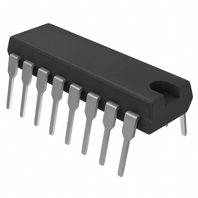
The 74HCT173N,652 is a D-Type flip-flop logic integrated circuit manufactured by NXP USA Inc., designed for 4-bit parallel data storage with positive edge triggering and tri-state output capability. This component operates within the 74HCT logic family standard and is housed in a 16-DIP through-hole package. The part is currently classified as obsolete, making identification of functionally equivalent substitutes essential for system maintenance, repair, and legacy design support.
Substiute Parts
Key Parameters
| Parameter | Value |
|---|---|
| Manufacturer Part Number | 74HCT173N,652 |
| Manufacturer | NXP USA Inc. |
| Category | Logic |
| Description | IC FF D-TYPE SNGL 4BIT 16DIP |
| Type | D-Type Flip-Flop |
| Number of Elements | 1 |
| Number of Bits per Element | 4 |
| Output Type | Tri-State, Non-Inverted |
| Trigger Type | Positive Edge |
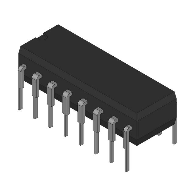
| Package / Case | 16-DIP (0.300", 7.62mm) |
| Mounting Type | Through Hole |
| Voltage - Supply | 4.5V ~ 5.5V |
| Operating Temperature | -40°C ~ 125°C (TA) |
| Product Status | Obsolete |
Substitute Part Grouping Explanation
Substitution eligibility for the 74HCT173N,652 is determined by strict adherence to the following core parameters:
Critical Matching Parameters:
- Logic family: 74HCT series
- Function: D-Type flip-flop with master reset capability
- Configuration: Single element, 4-bit storage
- Output architecture: Tri-state, non-inverted
- Trigger mechanism: Positive edge
- Package format: 16-DIP (0.300", 7.62mm)
- Mounting technology: Through hole
- Supply voltage range: 4.5V ~ 5.5V
- Temperature operating range: Minimum -40°C or lower, maximum 125°C or higher
The CD74HCT173E qualifies as a direct functional substitute based on matching all critical parameters. Both parts share identical logic family designation, flip-flop architecture, bit configuration, output type, trigger mechanism, package specification, and supply voltage requirements. Differences in secondary parameters such as clock frequency, propagation delay specifications, quiescent current, and input capacitance do not preclude substitution when the primary functional and electrical requirements are met.
Parameter Comparison
| Parameter | 74HCT173N,652 (NXP) | CD74HCT173E (Harris) | Compatibility Notes |
|---|---|---|---|
| Manufacturer Part Number | 74HCT173N,652 | CD74HCT173E | Different part numbers, same base product |
| Series | 74HCT | 74HCT | Identical logic family |
| Type | D-Type | D-Type | Identical flip-flop architecture |
| Number of Elements | 1 | 1 | Identical configuration |
| Number of Bits per Element | 4 | 4 | Identical bit width |
| Output Type | Tri-State, Non-Inverted | Tri-State, Non-Inverted | Identical output architecture |
| Trigger Type | Positive Edge | Positive Edge | Identical trigger mechanism |
| Clock Frequency | 80 MHz | 60 MHz | NXP rated higher; Harris part acceptable for most applications |
| Max Propagation Delay @ V, Max CL | 40ns @ 4.5V, 50pF | 40ns @ 4.5V, 50pF | Identical timing specification |
| Current - Output High, Low | 6mA, 6mA | 6mA, 6mA | Identical output current capability |
| Voltage - Supply | 4.5V ~ 5.5V | 4.5V ~ 5.5V | Identical supply voltage range |
| Current - Quiescent (Iq) | 4 µA | 8 µA | Harris part draws twice the quiescent current |
| Input Capacitance | 3.5 pF | 10 pF | Harris part has higher input capacitance |
| Operating Temperature | -40°C ~ 125°C | -55°C ~ 125°C | Harris part rated for lower minimum temperature |
| Package / Case | 16-DIP (0.300", 7.62mm) | 16-DIP (0.300", 7.62mm) | Identical package footprint and pinout |
| Mounting Type | Through Hole | Through Hole | Identical mounting technology |
Engineering Selection Recommendations
Primary Part (74HCT173N,652 - NXP USA Inc.): The original NXP part is classified as obsolete. Current inventory availability is limited to existing stock (1117 pcs reported). This part carries RoHS3 compliance certification and REACH unaffected status, meeting modern environmental and regulatory requirements. Selection of this part is appropriate only when existing stock is accessible and regulatory compliance documentation is required.
Substitute Part (CD74HCT173E - Harris Corporation): The Harris CD74HCT173E provides functional equivalence across all critical logic and electrical parameters. This part is also classified as obsolete but maintains higher current inventory levels (2071 pcs reported). The Harris part is RoHS non-compliant and does not carry REACH certification, which may present regulatory constraints in applications subject to environmental compliance mandates. The extended operating temperature range (-55°C minimum versus -40°C) provides additional thermal margin for applications requiring operation at lower ambient temperatures. Higher quiescent current (8 µA versus 4 µA) and input capacitance (10 pF versus 3.5 pF) are secondary considerations that do not affect functional substitution in standard logic applications.
Selection Criteria:
- Choose the NXP part when RoHS3 compliance and REACH certification are mandatory requirements.
- Choose the Harris part when extended low-temperature operation (-55°C) is required and regulatory compliance is not a constraint.
- Both parts are suitable for direct pin-for-pin replacement in 16-DIP through-hole circuit board designs.
Frequently Asked Questions (FAQ)
Q: Can the CD74HCT173E directly replace the 74HCT173N,652 in an existing circuit?
A: Yes. Both parts share identical pinout, package footprint, logic family designation, and core electrical specifications. Direct pin-for-pin replacement is supported without circuit modification. Verify that regulatory compliance requirements (RoHS, REACH) do not restrict use of the Harris part in your application.
Q: What is the significance of the different clock frequency ratings (80 MHz vs. 60 MHz)?
A: The NXP part is rated for 80 MHz maximum clock frequency, while the Harris part is rated for 60 MHz. In applications operating below 60 MHz, both parts are functionally equivalent. Applications requiring operation between 60 MHz and 80 MHz must use the NXP part. Most legacy logic applications operate well below these frequencies, making this difference non-critical for typical substitution scenarios.
Q: Why does the Harris part have higher quiescent current (8 µA vs. 4 µA)?
A: Quiescent current variation reflects manufacturing process differences between NXP and Harris. The 4 µA difference is negligible in most applications. This becomes relevant only in ultra-low-power designs where every microampere of standby current is critical. For standard logic applications, this difference does not affect system performance.
Q: Are there any temperature-related constraints when substituting these parts?
A: The Harris part extends the minimum operating temperature to -55°C compared to the NXP part's -40°C minimum. Both parts support the same maximum temperature of 125°C. If your application requires operation below -40°C, the Harris part provides additional thermal margin. Standard industrial and commercial applications typically operate within the -40°C to 125°C range, where both parts are equivalent.
Q: What does "RoHS non-compliant" mean for the Harris part?
A: The Harris CD74HCT173E does not meet RoHS (Restriction of Hazardous Substances) compliance standards. If your application, customer, or regulatory jurisdiction requires RoHS certification, you must use the NXP part. Verify compliance requirements before selecting the Harris substitute.
Q: Can I use either part interchangeably in a design that will be manufactured in volume?
A: Both parts are classified as obsolete, meaning neither manufacturer actively produces them. Volume manufacturing should not rely on either part. For new designs, evaluate modern logic family alternatives such as 74LVC or 74AUC series, which offer active production status, improved power efficiency, and broader availability. For legacy system repairs or limited-quantity applications, either part may be used subject to compliance and availability constraints.
Q: What is the difference between the NXP packaging designation "16-DIP" and the Harris designation "16-PDIP"?
A: Both designations refer to the same physical package: a 16-pin dual inline package with 0.300-inch (7.62mm) row spacing. The "P" in "16-PDIP" indicates plastic material, which is standard for both parts. The packages are mechanically and electrically identical, supporting direct substitution.
Alternative Parts

SJ6012L2TP
Littelfuse Inc.
6 Alternative Parts

JMK107BBJ476MA-RE
Taiyo Yuden
10 Alternative Parts

GMK107BBJ475MA-T
Taiyo Yuden
5 Alternative Parts
SJ6020N2ARP
Littelfuse Inc.
3 Alternative Parts
SJ6025R2ATP
Littelfuse Inc.
4 Alternative Parts

2474-05L
API Delevan Inc.
1 Alternative Parts

4590R-684K
API Delevan Inc.
1 Alternative Parts

CM6560R-334
API Delevan Inc.
1 Alternative Parts

CM6460-104
API Delevan Inc.
1 Alternative Parts

5526-12
API Delevan Inc.
1 Alternative Parts