


Request Quote
(Ships tomorrow)
74ACT109PC Equivalent & Substitute Parts
Part Overview
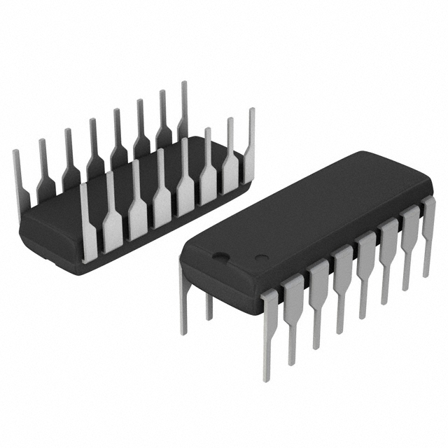
The 74ACT109PC is a dual JK-type flip-flop logic integrated circuit manufactured by onsemi, housed in a 16-DIP package. This component provides two independent 1-bit JK flip-flops with complementary outputs, set/preset and reset functionality, and positive edge triggering. The product is classified as obsolete, making equivalent substitute parts necessary for ongoing system maintenance, repairs, and legacy design support.
Substiute Parts
Key Parameters
| Parameter | Value |
|---|---|
| Manufacturer Part Number | 74ACT109PC |
| Manufacturer | onsemi |
| Series | 74ACT |
| Type | JK Type Flip-Flop |
| Number of Elements | 2 |
| Number of Bits per Element | 1 |
| Output Type | Complementary |
| Trigger Type | Positive Edge |
| Clock Frequency | 210 MHz |
| Max Propagation Delay | 11 ns @ 5V, 50pF |
| Voltage Supply Range | 4.5V ~ 5.5V |
| Current Output High/Low | 24mA / 24mA |
| Quiescent Current | 20 µA |
| Operating Temperature | -40°C ~ 85°C |
| Package Type | 16-DIP (0.300", 7.62mm) |
| Mounting Type | Through Hole |
| Product Status | Obsolete |
Substitute Part Grouping Explanation
Substitution eligibility for the 74ACT109PC is determined by strict adherence to the following electrical and mechanical parameters:
Critical Matching Parameters:
- Logic family and series (74ACT)
- Flip-flop type (JK Type)
- Number of elements (2) and bits per element (1)
- Output configuration (Complementary)
- Trigger mechanism (Positive Edge)
- Package type (16-DIP, 0.300", 7.62mm)
- Mounting type (Through Hole)
- Supply voltage range (4.5V ~ 5.5V)
Allowable Variation Parameters:
- Clock frequency (may differ; substitute must meet or exceed application requirements)
- Propagation delay (may differ; substitute must meet or exceed timing requirements)
- Quiescent current (may differ; substitute specifications acceptable if within system power budget)
- Operating temperature range (may differ; substitute must cover application temperature range)
- Input capacitance (may differ; acceptable if within system loading constraints)
The CD74ACT109E qualifies as a direct substitute based on matching all critical parameters while maintaining functional and electrical compatibility.
Parameter Comparison
| Parameter | 74ACT109PC (onsemi) | CD74ACT109E (Harris Corporation) | Compatibility |
|---|---|---|---|
| Series | 74ACT | 74ACT | Match |
| Type | JK Type | JK Type | Match |
| Number of Elements | 2 | 2 | Match |
| Number of Bits per Element | 1 | 1 | Match |
| Output Type | Complementary | Complementary | Match |
| Trigger Type | Positive Edge | Positive Edge | Match |
| Clock Frequency | 210 MHz | 100 MHz | Substitute lower; verify application requirement |
| Max Propagation Delay @ 5V, 50pF | 11 ns | 10.3 ns | Substitute faster; acceptable |
| Voltage Supply Range | 4.5V ~ 5.5V | 4.5V ~ 5.5V | Match |
| Current Output High/Low | 24mA / 24mA | 24mA / 24mA | Match |
| Quiescent Current | 20 µA | 4 µA | Substitute lower; beneficial |
| Input Capacitance | 4.5 pF | 10 pF | Substitute higher; verify system loading |
| Operating Temperature Range | -40°C ~ 85°C | -55°C ~ 125°C | Substitute wider; acceptable |
| Package Type | 16-DIP (0.300", 7.62mm) | 16-DIP (0.300", 7.62mm) | Match |
| Mounting Type | Through Hole | Through Hole | Match |
| Product Status | Obsolete | Obsolete | Both obsolete |
Engineering Selection Recommendations
Primary Substitute: CD74ACT109E
The CD74ACT109E manufactured by Harris Corporation is a direct functional and electrical equivalent to the 74ACT109PC. Both components are classified as obsolete, requiring substitution for system continuity.
Selection Basis:
- Identical logic family, flip-flop configuration, and package specifications
- Matching supply voltage range and output drive capability
- Propagation delay of 10.3 ns is superior to the original 11 ns specification
- Quiescent current of 4 µA is lower than the original 20 µA, reducing power consumption
- Extended operating temperature range (-55°C ~ 125°C) provides broader environmental coverage than the original (-40°C ~ 85°C)
- Input capacitance of 10 pF is higher than the original 4.5 pF; system loading analysis required if input drive capability is marginal
- Clock frequency specification of 100 MHz is lower than the original 210 MHz; application timing requirements must be confirmed to ensure compatibility
Compliance Considerations:
- CD74ACT109E is RoHS non-compliant; verify compliance requirements for your application
- Both parts carry ECCN EAR99 classification and HTSUS code 8542.39.0001
Frequently Asked Questions (FAQ)
Q: Can the CD74ACT109E directly replace the 74ACT109PC in my circuit?
A: Yes, the CD74ACT109E is a direct substitute. Both components share identical logic family, flip-flop type, output configuration, trigger mechanism, and 16-DIP package specifications. Pin-for-pin compatibility is assured. However, verify that your application's clock frequency requirement does not exceed 100 MHz, as the substitute has a lower maximum clock frequency than the original.
Q: What is the difference in clock frequency between these parts?
A: The 74ACT109PC operates at 210 MHz maximum, while the CD74ACT109E operates at 100 MHz maximum. If your application requires clock frequencies above 100 MHz, the CD74ACT109E is not suitable. Confirm your actual system clock frequency requirement before substitution.
Q: Does the higher input capacitance of the CD74ACT109E affect my circuit?
A: The CD74ACT109E has 10 pF input capacitance compared to 4.5 pF for the original. This difference may impact circuits with marginal input drive capability or very high-impedance signal sources. Analyze your input driver specifications to confirm adequate drive current at your operating frequency.
Q: Why is the CD74ACT109E RoHS non-compliant?
A: The CD74ACT109E is an obsolete component manufactured before RoHS compliance became standard. If your application or supply chain requires RoHS compliance, this substitute may not be acceptable. Verify compliance requirements with your procurement and regulatory teams.
Q: Are there any temperature range considerations?
A: The CD74ACT109E operates from -55°C to 125°C, which is wider than the original 74ACT109PC range of -40°C to 85°C. This provides additional margin for extreme environmental conditions. If your application operates within the original temperature range, the substitute is fully compatible.
Q: Is the improved propagation delay of the CD74ACT109E beneficial?
A: Yes. The CD74ACT109E has a propagation delay of 10.3 ns compared to 11 ns for the original. This faster response time is beneficial for timing-critical applications and poses no compatibility risk.
Q: Will the lower quiescent current of the CD74ACT109E affect my design?
A: No. The CD74ACT109E draws 4 µA quiescent current versus 20 µA for the original. This reduction in standby power consumption is advantageous and does not introduce any compatibility issues.
Alternative Parts

SJ6012L2TP
Littelfuse Inc.
6 Alternative Parts

JMK107BBJ476MA-RE
Taiyo Yuden
10 Alternative Parts

GMK107BBJ475MA-T
Taiyo Yuden
5 Alternative Parts
SJ6020N2ARP
Littelfuse Inc.
3 Alternative Parts
SJ6025R2ATP
Littelfuse Inc.
4 Alternative Parts

2474-05L
API Delevan Inc.
1 Alternative Parts

4590R-684K
API Delevan Inc.
1 Alternative Parts

CM6560R-334
API Delevan Inc.
1 Alternative Parts

CM6460-104
API Delevan Inc.
1 Alternative Parts

5526-12
API Delevan Inc.
1 Alternative Parts