


Request Quote
(Ships tomorrow)
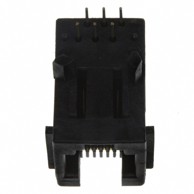
Amphenol ICC 68898-001 Modular Connector Jack 6P6C RJ11/RJ12/RJ14/RJ25 90° Unshielded Equivalent & Substitute Parts
Part Overview
The Amphenol ICC 68898-001 is a modular connector jack with 6 positions and 6 contacts (6P6C) in a 90-degree right-angle orientation, designed for RJ11, RJ12, RJ14, and RJ25 applications. This connector features through-hole solder termination, unshielded construction, and Category 3 ratings suitable for telecommunications and data communication applications.
The 68898-001 carries an obsolete part status. Identifying equivalent and substitute parts is necessary to maintain design continuity, ensure supply chain availability, and support ongoing production requirements. Substitute parts must maintain electrical and mechanical compatibility while meeting current manufacturing and compliance standards.
Substiute Parts
Key Parameters
| Parameter | Specification |
|---|---|
| Connector Type | Jack Modular Connector |
| Positions/Contacts | 6P6C (RJ11, RJ12, RJ14, RJ25) |
| Orientation | 90° Angle (Right) |
| Mounting Type | Through Hole |
| Termination | Solder |
| Shielding | Unshielded |
| Number of Ports | 1 |
| Number of Rows | 1 |
| Contact Material | Copper Alloy |
| Contact Finish | Gold |
| Housing Material | Polyamide (PA), Nylon |
| Operating Temperature Range | -40°C to 70°C |
| Tab Direction | Down |
| Features | Board Guide, Panel Stops |
Substitute Part Grouping Explanation
Substitute parts for the 68898-001 are grouped into two categories based on shielding configuration:
Category A: Unshielded Direct Equivalents These parts maintain the unshielded electrical configuration of the original 68898-001. Substitution is based on matching the following critical parameters: 6P6C contact configuration, 90-degree right-angle orientation, through-hole solder termination, single port/single row design, and down tab direction. Parts in this category are electrically and mechanically interchangeable for applications not requiring EMI shielding.
Category B: Shielded Alternatives These parts provide shielded construction with EMI finger protection. Substitution into this category is appropriate only when the application design permits or requires electromagnetic interference mitigation. Shielded variants maintain the same 6P6C configuration, 90-degree orientation, through-hole termination, and mechanical form factor, but introduce shielding and EMI fingers as additional features.
Key parameters determining substitution eligibility:
- Contact configuration: 6P6C (RJ11/RJ12/RJ14/RJ25 compatible)
- Orientation: 90° right-angle
- Mounting: Through-hole solder
- Port/Row configuration: 1 port, 1 row
- Tab direction: Down
- Connector type: Jack modular
Parameter Comparison
| Part Number | Manufacturer | Shielding | Contact Material | Contact Finish Thickness | Housing Material | Operating Temp | Product Status | RoHS Status |
|---|---|---|---|---|---|---|---|---|
| 68898-001 | Amphenol ICC (FCI) | Unshielded | Copper Alloy | 5.00µin (0.127µm) | Polyamide (PA), Nylon | -40°C to 70°C | Obsolete | Non-compliant |
| 68898-001LF | Amphenol ICC (FCI) | Unshielded | Copper Alloy | 5.00µin (0.127µm) | Polyamide (PA), Nylon | -40°C to 70°C | Active | Compliant |
| 5520250-3 | TE Connectivity AMP | Unshielded | Phosphor Bronze | 50.0µin (1.27µm) | Polybutylene Terephthalate (PBT), Polyester | -40°C to 85°C | Active | Compliant |
| SS-6466S-A-PG1-BB-50 | Stewart Connector | Shielded, EMI Finger | Copper Alloy | 50.0µin (1.27µm) | Thermoplastic | -40°C to 85°C | Active | ROHS3 Compliant |
| SS-6466S-A-PG4-BA | Stewart Connector | Shielded, EMI Finger | Copper Alloy | 30.0µin (0.76µm) | Thermoplastic | -40°C to 85°C | Active | ROHS3 Compliant |
| SS-6466S-A-PG4-BA-50 | Stewart Connector | Shielded, EMI Finger | Copper Alloy | 50.0µin (1.27µm) | Thermoplastic | -40°C to 85°C | Active | ROHS3 Compliant |
| SS-6466S-A-PGFLS | Stewart Connector | Shielded | Copper Alloy | 30.0µin (0.76µm) | Thermoplastic | -40°C to 85°C | Active | ROHS3 Compliant |
| SS-6466S-A-PGFLS-BB | Stewart Connector | Shielded, EMI Finger | Copper Alloy | 30.0µin (0.76µm) | Thermoplastic | -40°C to 85°C | Active | ROHS3 Compliant |
| SS63600-005F | Stewart Connector | Unshielded | Copper Alloy | 30.0µin (0.76µm) | Thermoplastic | -40°C to 85°C | Active | ROHS3 Compliant |
Engineering Selection Recommendations
Primary Recommendation: 68898-001LF
The 68898-001LF is the direct equivalent replacement for the obsolete 68898-001. Both parts share identical electrical and mechanical specifications: 6P6C configuration, 90-degree right-angle orientation, through-hole solder termination, unshielded design, and copper alloy contacts with gold finish. The 68898-001LF carries active product status and RoHS compliance, addressing the obsolescence and regulatory requirements of the original part. This part maintains the same housing material (Polyamide/Nylon) and operating temperature range (-40°C to 70°C). Selection of 68898-001LF requires no design modifications and provides direct form-fit-function compatibility.
Secondary Recommendation for Enhanced Performance: 5520250-3
The TE Connectivity 5520250-3 provides an unshielded 6P6C modular jack with identical mechanical form factor and orientation. This part offers an extended operating temperature range (-40°C to 85°C) compared to the original specification, enhanced contact durability through phosphor bronze material, and increased contact finish thickness (50.0µin versus 5.00µin). The 5520250-3 is RoHS compliant and carries active product status. Selection of this part is appropriate when improved thermal performance or extended contact life is required within the same unshielded electrical architecture.
Shielded Alternatives: SS-6466S Series
The Stewart Connector SS-6466S series (SS-6466S-A-PG1-BB-50, SS-6466S-A-PG4-BA, SS-6466S-A-PG4-BA-50, SS-6466S-A-PGFLS, SS-6466S-A-PGFLS-BB) provides shielded construction with EMI finger protection. These parts maintain the 6P6C configuration, 90-degree orientation, and through-hole solder termination. Selection into the shielded category is appropriate only when the application design requires electromagnetic interference mitigation. All SS-6466S variants carry active product status and ROHS3 compliance. Contact finish thickness varies between 30.0µin and 50.0µin across variants.
Unshielded Alternative: SS63600-005F
The Stewart Connector SS63600-005F provides an unshielded 6P6C modular jack with extended operating temperature range (-40°C to 85°C), thermoplastic housing, and ROHS3 compliance. This part includes waterproof ingress protection and board lock features. Selection is appropriate when enhanced environmental protection or extended thermal performance is required while maintaining unshielded electrical characteristics.
Frequently Asked Questions (FAQ)
Q: Can the 68898-001LF be used as a direct replacement for the obsolete 68898-001?
A: Yes. The 68898-001LF is electrically and mechanically identical to the 68898-001. Both parts feature 6P6C configuration, 90-degree right-angle orientation, through-hole solder termination, unshielded design, and identical contact materials and finishes. The primary differences are product status (active versus obsolete) and RoHS compliance. No design modifications are required.
Q: What is the difference between unshielded and shielded modular jacks in this product line?
A: Unshielded parts (68898-001, 68898-001LF, 5520250-3, SS63600-005F) provide standard electrical connectivity without electromagnetic interference protection. Shielded parts (SS-6466S series) incorporate shielding and EMI fingers to attenuate electromagnetic interference. Selection between unshielded and shielded depends on application requirements. Shielded variants are not interchangeable with unshielded variants in designs that do not accommodate the additional shielding structure.
Q: Are all substitute parts compatible with RJ11, RJ12, RJ14, and RJ25 standards?
A: Yes. All parts listed maintain 6P6C contact configuration, which is compatible with RJ11, RJ12, RJ14, and RJ25 modular connector standards. The 6-position, 6-contact arrangement is the common electrical interface across these standards.
Q: What is the significance of contact finish thickness differences?
A: Contact finish thickness affects contact durability and wear resistance. The original 68898-001 specifies 5.00µin (0.127µm) gold finish. Substitute parts offer thicker finishes: 30.0µin (0.76µm) or 50.0µin (1.27µm). Thicker finishes provide extended contact life and improved resistance to corrosion and wear. Selection of thicker finishes is appropriate for applications requiring enhanced reliability or extended service life.
Q: What is the difference between Polyamide (PA) Nylon housing and Thermoplastic housing?
A: The original 68898-001 uses Polyamide (PA) Nylon housing. Substitute parts employ Thermoplastic housing materials, which may include polybutylene terephthalate (PBT) or other thermoplastic polymers. Both material classes provide adequate mechanical support and electrical insulation for modular connector applications. Material selection does not affect electrical compatibility but may influence environmental resistance and mechanical properties.
Q: Can the TE Connectivity 5520250-3 be used in place of the Amphenol 68898-001LF?
A: Yes, with consideration of material and temperature differences. Both parts maintain identical 6P6C configuration, 90-degree orientation, through-hole solder termination, and unshielded design. The 5520250-3 offers extended operating temperature range (-40°C to 85°C versus -40°C to 70°C) and phosphor bronze contacts with thicker gold finish (50.0µin). Selection of the 5520250-3 is appropriate when enhanced thermal performance or contact durability is required. No design modifications are necessary for mechanical compatibility.
Q: What does "Board Lock" feature mean in the context of modular connectors?
A: Board Lock is a mechanical feature that provides positive retention of the connector to the printed circuit board during assembly and operation. This feature prevents accidental disconnection or movement of the connector. The original 68898-001 includes Board Guide and Panel Stops features. Substitute parts may include Board Lock in addition to or instead of these features. The presence of Board Lock does not affect electrical compatibility but enhances mechanical security.
Q: Are all substitute parts RoHS compliant?
A: The original 68898-001 is RoHS non-compliant. The 68898-001LF is RoHS compliant. The TE Connectivity 5520250-3 is RoHS compliant. All Stewart Connector parts (SS-6466S series and SS63600-005F) are ROHS3 compliant. Selection of RoHS-compliant parts is necessary for applications subject to RoHS regulations or customer requirements.
Q: What is the difference between REACH Affected and REACH Unaffected status?
A: REACH Affected indicates that the part contains substances of very high concern (SVHC) listed under the REACH regulation and requires compliance documentation. REACH Unaffected indicates that the part does not contain listed SVHC substances. The 68898-001LF carries REACH Affected status, while TE Connectivity and Stewart Connector parts carry REACH Unaffected status. Selection of REACH Unaffected parts simplifies compliance documentation for applications subject to REACH regulations.
Q: Can shielded modular jacks (SS-6466S series) be used in designs originally specified for unshielded connectors?
A: Shielded parts can be used only if the printed circuit board layout and mechanical design accommodate the additional shielding structure. Shielded variants have different physical dimensions and mounting requirements compared to unshielded parts. Design review and potential PCB layout modifications are necessary before substituting shielded parts into designs originally specified for unshielded connectors. Electrical compatibility is maintained, but mechanical compatibility must be verified.
Alternative Parts

SJ6012L2TP
Littelfuse Inc.
6 Alternative Parts

JMK107BBJ476MA-RE
Taiyo Yuden
10 Alternative Parts

GMK107BBJ475MA-T
Taiyo Yuden
5 Alternative Parts
SJ6020N2ARP
Littelfuse Inc.
3 Alternative Parts
SJ6025R2ATP
Littelfuse Inc.
4 Alternative Parts

2474-05L
API Delevan Inc.
1 Alternative Parts

4590R-684K
API Delevan Inc.
1 Alternative Parts

CM6560R-334
API Delevan Inc.
1 Alternative Parts

CM6460-104
API Delevan Inc.
1 Alternative Parts

5526-12
API Delevan Inc.
1 Alternative Parts