


Request Quote
(Ships tomorrow)
Littelfuse 5KP75C Transient Voltage Suppressor - Equivalent & Substitute Parts
Part Overview
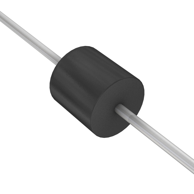
The Littelfuse 5KP75C is a bidirectional transient voltage suppressor (TVS) diode designed for general-purpose overvoltage protection applications. This component features a 75V reverse standoff voltage rating with 5000W peak pulse power handling capability in a through-hole P600 axial package. The 5KP75C is classified as obsolete, necessitating identification of active equivalent alternatives that maintain electrical and mechanical compatibility for ongoing system support and new designs.
Substiute Parts
Key Parameters
| Parameter | Value |
|---|---|
| Manufacturer Part Number | 5KP75C |
| Manufacturer | Littelfuse |
| Category | Transient Voltage Suppressors (TVS) |
| Type | Zener |
| Bidirectional Channels | 1 |
| Voltage - Reverse Standoff (Typ) | 75V |
| Voltage - Breakdown (Min) | 78.93V |
| Voltage - Clamping (Max) @ Ipp | 127.05V |
| Power - Peak Pulse | 5000W (5kW) |
| Mounting Type | Through Hole |
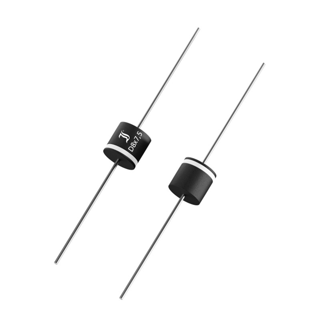
| Package / Case | P600, Axial |
| Operating Temperature Range | -55°C ~ 175°C (TJ) |
| RoHS Status | ROHS3 Compliant |
| Product Status | Obsolete |
Substitute Part Grouping Explanation
Substitution eligibility for the 5KP75C is determined by the following critical parameters:
- Voltage - Reverse Standoff (Typ): Must equal 75V
- Bidirectional Configuration: Must be 1 channel, bidirectional
- Type: Must be Zener TVS diode
- Mounting Type: Must be through-hole
- Power - Peak Pulse: Must be rated for 5000W or greater
- Operating Temperature Range: Must encompass -55°C to 175°C minimum
- RoHS Compliance: Must maintain ROHS3 compliance
The substitute parts identified below meet these core electrical and mechanical requirements. Variations in clamping voltage, breakdown voltage, and package form factor (P600 vs. R-6) are permissible within the scope of general-purpose TVS applications, provided the standoff voltage and power rating remain constant or exceed the original specification.
Parameter Comparison
| Parameter | 5KP75C (Littelfuse) | 5KP75CA (Diotec) | 15KP75CA-TP (Micro Commercial Co) | 30KP75CA-TP (Micro Commercial Co) | 5KP75CE3/TR13 (Microchip) |
|---|---|---|---|---|---|
| Voltage - Reverse Standoff (Typ) | 75V | 75V | 75V | 75V | 75V |
| Voltage - Breakdown (Min) | 78.93V | 83.3V | 83.3V | 83.8V | 83.3V |
| Voltage - Clamping (Max) @ Ipp | 127.05V | 121V | 122V | 119.4V | 134V |
| Power - Peak Pulse | 5000W | 5000W | 15000W | 30000W | 5000W |
| Bidirectional Channels | 1 | 1 | 1 | 1 | 1 |
| Mounting Type | Through Hole | Through Hole | Through Hole | Through Hole | Through Hole |
| Package / Case | P600, Axial | P600, Axial | R-6, Axial | R-6, Axial | P600, Axial |
| Operating Temperature Range | -55°C ~ 175°C | -50°C ~ 175°C | -55°C ~ 175°C | -55°C ~ 175°C | -55°C ~ 175°C |
| RoHS Status | ROHS3 Compliant | ROHS3 Compliant | ROHS3 Compliant | ROHS3 Compliant | ROHS3 Compliant |
| Product Status | Obsolete | Active | Active | Active | Active |
Engineering Selection Recommendations
Direct Package Compatibility (P600 Axial)
The 5KP75CA (Diotec Semiconductor) and 5KP75CE3/TR13 (Microchip Technology) maintain identical P600 axial package geometry to the original 5KP75C. Both are active products with ROHS3 compliance. The 5KP75CA operates at a minimum temperature of -50°C, which is 5°C higher than the original specification; applications requiring full -55°C operation should select the 5KP75CE3/TR13. The 5KP75CE3/TR13 exhibits a higher clamping voltage (134V) compared to the original (127.05V), which may be acceptable depending on circuit tolerance requirements.
Enhanced Power Rating Options (R-6 Axial)
The 15KP75CA-TP and 30KP75CA-TP (Micro Commercial Co) provide 15kW and 30kW peak pulse power ratings respectively, exceeding the original 5kW specification. These components use the R-6 axial package, which differs mechanically from the P600 package. Both maintain the 75V standoff voltage and full -55°C to 175°C operating range with ROHS3 compliance. Selection of these higher-power variants is appropriate for applications requiring increased transient energy absorption capacity.
Product Status Consideration
All identified substitute parts maintain active product status, ensuring long-term availability and supply chain stability compared to the obsolete 5KP75C.
Frequently Asked Questions (FAQ)
Q: Can I use the 15KP75CA-TP or 30KP75CA-TP as direct replacements for the 5KP75C?
A: Electrically, yes. Both maintain the 75V standoff voltage and exceed the 5kW power rating. However, the R-6 package differs from the original P600 package. PCB layout modifications may be required to accommodate the different package geometry. Verify mechanical fit before implementation.
Q: What is the significance of the different clamping voltages among the substitute parts?
A: Clamping voltage determines the maximum voltage transient that the TVS will allow across the protected circuit. The 5KP75C clamps at 127.05V, while substitutes range from 119.4V to 134V. Lower clamping voltages provide tighter protection; higher clamping voltages allow greater transient voltage. Select based on the protected circuit's voltage tolerance specifications.
Q: Why does the 5KP75CA have a minimum operating temperature of -50°C instead of -55°C?
A: This represents a manufacturer specification difference. For applications requiring operation at -55°C, select the 5KP75CE3/TR13 or the higher-power variants (15KP75CA-TP, 30KP75CA-TP), which all specify -55°C minimum operation.
Q: Are all substitute parts ROHS3 compliant?
A: Yes. All identified substitute parts maintain ROHS3 compliance, matching the environmental and regulatory status of the original 5KP75C.
Q: What is the difference between P600 and R-6 packages?
A: Both are through-hole axial packages for TVS diodes. P600 and R-6 differ in physical dimensions and lead spacing. The P600 package is used by the 5KP75C, 5KP75CA, and 5KP75CE3/TR13. The R-6 package is used by the 15KP75CA-TP and 30KP75CA-TP. PCB footprint compatibility must be verified before substitution.
Q: Can I substitute a higher power-rated part (15kW or 30kW) into a circuit designed for 5kW?
A: Yes. Higher power ratings provide additional transient energy absorption capacity without compromising circuit protection. The electrical characteristics (standoff voltage, clamping voltage, breakdown voltage) remain the same. Mechanical package compatibility must still be verified.
Alternative Parts

SJ6012L2TP
Littelfuse Inc.
6 Alternative Parts

JMK107BBJ476MA-RE
Taiyo Yuden
10 Alternative Parts

GMK107BBJ475MA-T
Taiyo Yuden
5 Alternative Parts
SJ6020N2ARP
Littelfuse Inc.
3 Alternative Parts
SJ6025R2ATP
Littelfuse Inc.
4 Alternative Parts

2474-05L
API Delevan Inc.
1 Alternative Parts

4590R-684K
API Delevan Inc.
1 Alternative Parts

CM6560R-334
API Delevan Inc.
1 Alternative Parts

CM6460-104
API Delevan Inc.
1 Alternative Parts

5526-12
API Delevan Inc.
1 Alternative Parts