


Request Quote
(Ships tomorrow)
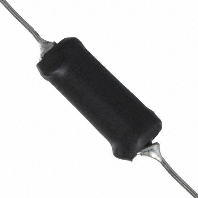
Bourns 5800-331 330µH Axial Inductor Equivalent & Substitute Parts
Part Overview
The Bourns 5800-331 is a 330 µH unshielded drum core wirewound inductor rated for 400 mA continuous current with 770 mOhm maximum DC resistance. This through-hole axial component operates across -55°C to 105°C and is designed for general-purpose filtering and energy storage applications in electronic circuits.
The 5800-331 carries obsolete product status. Identifying equivalent and substitute parts ensures design continuity and maintains supply chain reliability for legacy system maintenance and new production runs requiring compatible inductance characteristics.
Substiute Parts
Key Parameters
| Parameter | Value |
|---|---|
| Inductance | 330 µH |
| Tolerance | ±10% |
| Current Rating | 400 mA |
| DC Resistance (Max) | 770 mOhm |
| Current - Saturation | 600 mA |
| Core Material | Ferrite |
| Shielding | Unshielded |
| Operating Temperature Range | -55°C to 105°C |
| Mounting Type | Through Hole |
| Package | Axial |
| Size | 0.275" Dia × 0.700" L (6.99mm × 17.78mm) |
Substitute Part Grouping Explanation
Substitute parts for the 5800-331 are classified based on electrical and mechanical compatibility within the following criteria:
Direct Equivalent (Identical Electrical Specifications):
- Inductance: 330 µH ±10%
- Current Rating: 400 mA minimum
- DC Resistance: 770 mOhm maximum
- Core Material: Ferrite
- Shielding: Unshielded
- Mounting: Through Hole Axial
- Temperature Range: -55°C to 105°C minimum
Similar Substitute (Compatible Electrical Performance with Parameter Variations):
- Inductance: 330 µH (tolerance may vary)
- Current Rating: ≥400 mA
- DC Resistance: ≤770 mOhm preferred
- Core Material: Ferrite
- Shielding: Unshielded
- Mounting: Through Hole Axial
- Temperature Range: ≥-55°C to 105°C
Parameter Comparison
| Parameter | 5800-331 (Main) | 5800-331-RC (Direct) | 2474-31L (Similar) |
|---|---|---|---|
| Manufacturer | Bourns Inc. | Bourns Inc. | API Delevan Inc. |
| Inductance | 330 µH | 330 µH | 330 µH |
| Tolerance | ±10% | ±10% | ±15% |
| Current Rating (Amps) | 400 mA | 400 mA | 740 mA |
| Current - Saturation | 600 mA | 600 mA | 350 mA |
| DC Resistance (Max) | 770 mOhm | 770 mOhm | 650 mOhm |
| Core Material | Ferrite | Ferrite | Ferrite |
| Type | Drum Core, Wirewound | Drum Core, Wirewound | Molded |
| Shielding | Unshielded | Unshielded | Unshielded |
| Operating Temperature | -55°C to 105°C | -55°C to 105°C | -55°C to 125°C |
| Mounting Type | Through Hole | Through Hole | Through Hole |
| Package / Case | Axial | Axial | Axial |
| Size / Dimension | 0.275" Dia × 0.700" L (6.99mm × 17.78mm) | 0.275" Dia × 0.700" L (6.99mm × 17.78mm) | 0.240" Dia × 0.740" L (6.10mm × 18.80mm) |
| Product Status | Obsolete | Active | Active |
| RoHS Status | RoHS non-compliant | ROHS3 Compliant | RoHS non-compliant |
Engineering Selection Recommendations
5800-331-RC (Bourns Inc.) is the primary direct substitute. This part maintains identical electrical specifications and physical dimensions while offering active product status and ROHS3 compliance. Selection of 5800-331-RC eliminates obsolescence risk and provides regulatory alignment for new designs or production transitions.
2474-31L (API Delevan Inc.) serves as a compatible alternative when higher current capacity is acceptable. This molded inductor provides 740 mA continuous current rating versus 400 mA, lower DC resistance (650 mOhm vs. 770 mOhm), and extended temperature range (-55°C to 125°C). Physical dimensions differ slightly (0.240" Dia × 0.740" L). The ±15% inductance tolerance and lower saturation current (350 mA vs. 600 mA) require circuit-level verification. This part maintains active status but does not meet RoHS3 compliance.
Component selection depends on regulatory requirements, thermal environment, and available PCB space. Direct substitution with 5800-331-RC is recommended for legacy system maintenance. The 2474-31L alternative requires design validation for saturation and tolerance parameters.
Frequently Asked Questions (FAQ)
Q: Can 5800-331-RC replace 5800-331 in existing designs without modification?
A: Yes. The 5800-331-RC maintains identical inductance (330 µH ±10%), current rating (400 mA), DC resistance (770 mOhm max), and physical dimensions (0.275" Dia × 0.700" L). Through-hole axial mounting is identical. No circuit modifications are required.
Q: What are the key differences between 5800-331-RC and 2474-31L?
A: Both parts provide 330 µH inductance with ferrite cores and unshielded axial construction. The 5800-331-RC matches the original 400 mA current rating and 770 mOhm DC resistance. The 2474-31L offers higher current capacity (740 mA) and lower DC resistance (650 mOhm) but has wider inductance tolerance (±15% vs. ±10%), lower saturation current (350 mA vs. 600 mA), and slightly different physical dimensions (0.240" Dia × 0.740" L).
Q: Is the 2474-31L suitable for applications requiring 400 mA continuous current?
A: The 2474-31L is rated for 740 mA continuous current, exceeding the 400 mA requirement. However, its saturation current is 350 mA, which is lower than the original part's 600 mA saturation rating. Circuit analysis is required to confirm saturation margin is acceptable for the intended application.
Q: What compliance differences exist between substitute options?
A: The 5800-331-RC is ROHS3 compliant, meeting current regulatory requirements. Both the original 5800-331 and 2474-31L are RoHS non-compliant. For applications requiring RoHS compliance, 5800-331-RC is the only qualified option.
Q: Are there physical space constraints when using 2474-31L?
A: The 2474-31L dimensions (0.240" Dia × 0.740" L / 6.10mm × 18.80mm) differ from the original (0.275" Dia × 0.700" L / 6.99mm × 17.78mm). The substitute is narrower but slightly longer. PCB layout verification is necessary to confirm fit within available space.
Q: What is the inductance tolerance impact of using 2474-31L?
A: The 2474-31L carries ±15% tolerance versus ±10% for the original part. This wider tolerance may affect circuit performance in applications with tight inductance specifications. Circuit simulation or testing is recommended to validate performance across the tolerance range.
Alternative Parts

SJ6012L2TP
Littelfuse Inc.
6 Alternative Parts

JMK107BBJ476MA-RE
Taiyo Yuden
10 Alternative Parts

GMK107BBJ475MA-T
Taiyo Yuden
5 Alternative Parts
SJ6020N2ARP
Littelfuse Inc.
3 Alternative Parts
SJ6025R2ATP
Littelfuse Inc.
4 Alternative Parts

2474-05L
API Delevan Inc.
1 Alternative Parts

4590R-684K
API Delevan Inc.
1 Alternative Parts

CM6560R-334
API Delevan Inc.
1 Alternative Parts

CM6460-104
API Delevan Inc.
1 Alternative Parts

5526-12
API Delevan Inc.
1 Alternative Parts