


Request Quote
(Ships tomorrow)
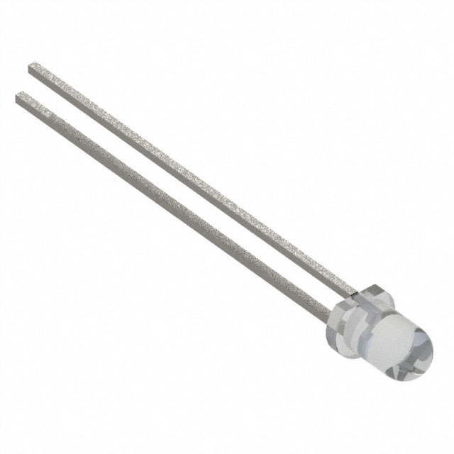
LED GREEN CLEAR T-1 T/H 3UGC-S Equivalent & Substitute Parts
Part Overview
The 3UGC-S is an active green LED indication component manufactured by Bivar Inc., designed for through-hole mounting applications. This discrete radial LED operates at a forward voltage of 2.1V with a test current of 20mA, delivering 200 millicandela brightness in a 3mm T-1 package format. The component features a clear, colorless domed lens with a 30° viewing angle and is ROHS3 compliant with unlimited moisture sensitivity rating (MSL 1).
Equivalent and substitute parts are identified when component availability changes, manufacturing discontinuation occurs, or inventory requirements necessitate alternative sourcing while maintaining functional compatibility within specified electrical and mechanical parameters.
Substiute Parts
Key Parameters
| Parameter | Value | Unit | Significance for Substitution |
|---|---|---|---|
| Lens Size | 3mm, T-1 | - | Physical form factor; determines PCB footprint compatibility |
| Mounting Type | Through Hole | - | Assembly method; radial lead configuration |
| Color | Green | - | Optical output specification |
| Lens Transparency | Clear | - | Optical clarity requirement |
| Voltage - Forward (Vf) | 2.1V | V | Circuit design parameter; determines series resistor values |
| Current - Test | 20mA | mA | Operating current specification |
| Millicandela Rating | 200mcd | mcd | Brightness output level |
| Viewing Angle | 30° | degrees | Light distribution pattern |
| Package / Case | Radial | - | Lead configuration and spacing |
| RoHS Status | ROHS3 Compliant | - | Environmental and regulatory compliance |
Substitute Part Grouping Explanation
Substitution compatibility for the 3UGC-S is determined by the following critical parameters:
Physical Compatibility Requirements:
- Lens size must remain 3mm T-1 format
- Mounting type must be through-hole with radial lead configuration
- Package case must be radial
Optical Compatibility Requirements:
- Color specification: Green
- Lens transparency: Clear
- Lens style: Round with domed top
Electrical Operating Parameters:
- Forward voltage (Vf): 2.1V nominal
- Test current: 20mA
- Millicandela rating: 200mcd
- Viewing angle: 30°
Regulatory Compliance:
- RoHS3 compliance required
- MSL rating: 1 (Unlimited)
The substitute part OVLBG4C7 manufactured by TT Electronics / Optek Technology is identified as an equivalent component. However, this substitute exhibits parameter variations that must be evaluated for specific application requirements: forward voltage of 3.2V (versus 2.1V), millicandela rating of 8400mcd (versus 200mcd), viewing angle of 45° (versus 30°), and maximum height of 5.35mm (versus 4.50mm).
Parameter Comparison
| Parameter | 3UGC-S (Bivar Inc.) | OVLBG4C7 (TT Electronics / Optek Technology) | Compatibility Notes |
|---|---|---|---|
| Manufacturer Part Number | 3UGC-S | OVLBG4C7 | Different manufacturers |
| Color | Green | Green | Match |
| Lens Size | 3mm, T-1 | 3mm, T-1 | Match |
| Lens Transparency | Clear | Clear | Match |
| Lens Style | Round with Domed Top | Round with Domed Top | Match |
| Mounting Type | Through Hole | Through Hole | Match |
| Package / Case | Radial | Radial | Match |
| Voltage - Forward (Vf) (Typ) | 2.1V | 3.2V | Variation: +1.1V |
| Current - Test | 20mA | 20mA | Match |
| Millicandela Rating | 200mcd | 8400mcd | Variation: +8200mcd (42x brighter) |
| Viewing Angle | 30° | 45° | Variation: +15° |
| Height (Max) | 4.50mm | 5.35mm | Variation: +0.85mm |
| RoHS Status | ROHS3 Compliant | ROHS3 Compliant | Match |
| MSL Rating | 1 (Unlimited) | 1 (Unlimited) | Match |
| Product Status | Active | Active | Both active |
Engineering Selection Recommendations
Primary Selection (3UGC-S): The 3UGC-S remains the preferred component when original specifications are required. This part is active, ROHS3 compliant, and maintains unlimited moisture sensitivity rating. Current inventory of 1086 pieces supports immediate availability.
Substitute Selection (OVLBG4C7): The OVLBG4C7 is classified as an equivalent substitute based on matching physical form factor, mounting type, and regulatory compliance. This component is also active and ROHS3 compliant with unlimited MSL rating. Inventory availability is significantly higher at 42,564 pieces.
Critical Parameter Variations Requiring Circuit Evaluation:
The OVLBG4C7 exhibits three significant electrical and optical parameter differences from the 3UGC-S:
-
Forward Voltage: 3.2V versus 2.1V represents a 1.1V increase. This variation requires recalculation of series resistor values in the LED drive circuit to maintain 20mA test current operation.
-
Brightness Output: 8400mcd versus 200mcd represents a 42-fold increase in luminous intensity. Applications requiring specific brightness levels must account for this substantial difference in optical output.
-
Viewing Angle: 45° versus 30° provides a wider light distribution pattern. This affects the spatial coverage of the LED indication in the application.
-
Physical Height: 5.35mm versus 4.50mm maximum height introduces a 0.85mm clearance consideration for PCB assembly and enclosure design.
Substitution Applicability: The OVLBG4C7 is suitable as a substitute when:
- Circuit design accommodates the 3.2V forward voltage requirement
- Increased brightness output (8400mcd) is acceptable or beneficial
- Wider viewing angle (45°) meets application requirements
- PCB layout and enclosure design accommodate the 5.35mm maximum height
Frequently Asked Questions (FAQ)
Q: Can OVLBG4C7 be used as a direct drop-in replacement for 3UGC-S?
A: Physical form factor compatibility exists (3mm T-1 through-hole radial package). However, the OVLBG4C7 requires circuit modification due to higher forward voltage (3.2V versus 2.1V). Series resistor values must be recalculated to maintain proper operating current. Direct substitution without circuit adjustment will result in incorrect LED brightness and potential component damage.
Q: What is the impact of the 1.1V forward voltage difference?
A: Forward voltage directly affects series resistor calculation. Using Ohm's law with a typical 5V supply: the 3UGC-S requires approximately 145Ω resistor, while the OVLBG4C7 requires approximately 95Ω resistor (both for 20mA operation). Incorrect resistor selection will alter LED brightness and operating current.
Q: Why is the OVLBG4C7 significantly brighter (8400mcd versus 200mcd)?
A: Millicandela rating reflects luminous intensity at the specified test current. The OVLBG4C7 is engineered for higher brightness output. Applications requiring the original 200mcd specification must account for this 42-fold difference in optical output, which may affect user perception and circuit design intent.
Q: Does the 45° viewing angle of OVLBG4C7 affect compatibility?
A: Viewing angle determines the cone of light distribution. The OVLBG4C7's 45° angle is wider than the 3UGC-S's 30° angle, providing broader light distribution. This is compatible with most applications but may alter the intended visual indication pattern in specific enclosure designs.
Q: Are both parts RoHS3 compliant?
A: Yes. Both 3UGC-S and OVLBG4C7 are ROHS3 compliant with MSL rating of 1 (Unlimited). Regulatory compliance is equivalent between the two components.
Q: What is the significance of the 0.85mm height difference?
A: The OVLBG4C7 maximum height is 5.35mm versus 3UGC-S at 4.50mm. This 0.85mm difference must be verified against PCB assembly clearance requirements and enclosure design constraints. Verify that the taller component does not interfere with overlying components or enclosure geometry.
Q: Which part should be selected for new designs?
A: For new designs, either component is acceptable based on application requirements. The 3UGC-S is suitable for applications requiring 200mcd brightness and 30° viewing angle. The OVLBG4C7 is suitable for applications requiring higher brightness (8400mcd) and wider viewing angle (45°). Circuit design must accommodate the respective forward voltage specifications.
Q: Is inventory availability a factor in substitution decisions?
A: Inventory levels are provided for reference: 3UGC-S has 1,086 pieces available, while OVLBG4C7 has 42,564 pieces available. Substitution may be necessary when primary component inventory is depleted. Verify that electrical and optical parameter variations are acceptable for the specific application before substituting based on availability alone.
Alternative Parts

SJ6012L2TP
Littelfuse Inc.
6 Alternative Parts

JMK107BBJ476MA-RE
Taiyo Yuden
10 Alternative Parts

GMK107BBJ475MA-T
Taiyo Yuden
5 Alternative Parts
SJ6020N2ARP
Littelfuse Inc.
3 Alternative Parts
SJ6025R2ATP
Littelfuse Inc.
4 Alternative Parts

2474-05L
API Delevan Inc.
1 Alternative Parts

4590R-684K
API Delevan Inc.
1 Alternative Parts

CM6560R-334
API Delevan Inc.
1 Alternative Parts

CM6460-104
API Delevan Inc.
1 Alternative Parts

5526-12
API Delevan Inc.
1 Alternative Parts