


Request Quote
(Ships tomorrow)
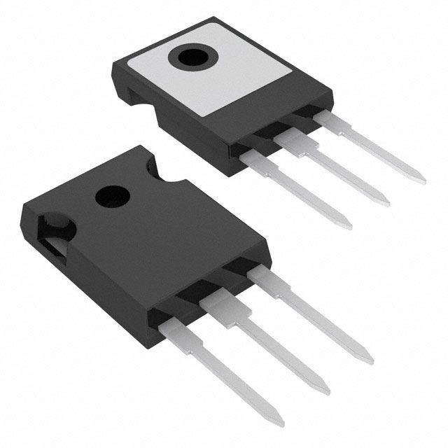
Equivalent & Substitute Parts for 30TPS08 SCR 800V 30A TO-247AC
Part Overview
The 30TPS08 is a silicon-controlled rectifier (SCR) rated for 800V off-state voltage and 30A RMS on-state current in a TO-247AC through-hole package. Manufactured by Vishay General Semiconductor - Diodes Division, this component is classified as obsolete. Due to its obsolete status and limited availability for new designs, identifying equivalent substitute parts with compatible electrical and mechanical characteristics is necessary for system continuity and procurement planning.
Substiute Parts
Key Parameters
| Parameter | Value |
|---|---|
| Voltage - Off State | 800 V |
| Voltage - Gate Trigger (Vgt) (Max) | 2 V |
| Current - Gate Trigger (Igt) (Max) | 45 mA |
| Voltage - On State (Vtm) (Max) | 1.3 V |
| Current - On State (It (RMS)) (Max) | 30 A |
| Current - Hold (Ih) (Max) | 100 mA |
| Current - Off State (Max) | 500 µA |
| Current - Non Rep. Surge 50, 60Hz (Itsm) | 300 A @ 50Hz |
| SCR Type | Standard Recovery |
| Operating Temperature | -40°C ~ 125°C |
| Mounting Type | Through Hole |
| Package / Case | TO-247-3 |
Substitute Part Grouping Explanation
Substitute parts for the 30TPS08 are selected based on the following criteria:
Primary Compatibility Parameters:
- SCR Type: Standard Recovery (all candidates match)
- Operating Temperature Range: -40°C ~ 125°C (all candidates match)
- Mounting Type: Through Hole (all candidates match)
- Package / Case: TO-247-3 form factor (all candidates match)
Electrical Performance Alignment:
- Off-state voltage rating must be equal to or greater than 800V
- On-state current (RMS) must be equal to or greater than 30A
- Gate trigger characteristics must be compatible with circuit requirements
- Hold current and off-state leakage must remain within acceptable operational limits
Two substitute parts meet these criteria: CS20-12IO1 (IXYS) and S8035KTP (Littelfuse Inc.).
Parameter Comparison
| Parameter | 30TPS08 (Vishay) | CS20-12IO1 (IXYS) | S8035KTP (Littelfuse) |
|---|---|---|---|
| Voltage - Off State | 800 V | 1.2 kV | 800 V |
| Voltage - Gate Trigger (Vgt) (Max) | 2 V | 1 V | 1.5 V |
| Current - Gate Trigger (Igt) (Max) | 45 mA | 65 mA | 40 mA |
| Voltage - On State (Vtm) (Max) | 1.3 V | 2.1 V | 1.8 V |
| Current - On State (It (RMS)) (Max) | 30 A | 30 A | 35 A |
| Current - Hold (Ih) (Max) | 100 mA | 100 mA | 50 mA |
| Current - Off State (Max) | 500 µA | 2 mA | 20 µA |
| Current - Non Rep. Surge 50, 60Hz (Itsm) | 300 A @ 50Hz | 200 A, 215 A | 425 A, 500 A |
| SCR Type | Standard Recovery | Standard Recovery | Standard Recovery |
| Operating Temperature | -40°C ~ 125°C | -40°C ~ 125°C | -40°C ~ 125°C |
| Mounting Type | Through Hole | Through Hole | Through Hole |
| Package / Case | TO-247-3 | TO-247-3 | TO-218-3 Isolated Tab |
| Product Status | Obsolete | Active | Active |
| RoHS Status | RoHS non-compliant | ROHS3 Compliant | ROHS3 Compliant |
Engineering Selection Recommendations
CS20-12IO1 (IXYS): This substitute provides a higher off-state voltage rating (1.2 kV vs. 800 V), which offers additional voltage margin in the application. The part maintains identical RMS current capability (30 A) and matching hold current (100 mA). The TO-247AD package is mechanically compatible with TO-247AC footprints. CS20-12IO1 is active in production and ROHS3 compliant, supporting long-term supply chain stability. Gate trigger voltage is lower (1 V max), which may reduce gate drive requirements. On-state voltage is higher (2.1 V max), resulting in increased power dissipation compared to the original part.
S8035KTP (Littelfuse Inc.): This substitute maintains the same off-state voltage rating (800 V) as the original 30TPS08, providing direct voltage compatibility. The part exceeds RMS current capability (35 A vs. 30 A) and offers superior surge current handling (425 A, 500 A vs. 300 A). S8035KTP is active in production and ROHS3 compliant. The TO-218 Isolated Tab package differs from the TO-247AC form factor, requiring PCB layout modification. Gate trigger voltage (1.5 V max) and on-state voltage (1.8 V max) are intermediate between the original and CS20-12IO1. Off-state leakage current is significantly lower (20 µA vs. 500 µA), improving efficiency in standby conditions.
Both substitutes are suitable for applications where the 30TPS08 is no longer available. Selection depends on specific circuit requirements regarding voltage margin, thermal management, and PCB layout constraints.
Frequently Asked Questions (FAQ)
Q: Can CS20-12IO1 be used as a direct replacement for 30TPS08 in all applications?
A: CS20-12IO1 is electrically compatible for applications where the 30TPS08 operates below 800V. The higher voltage rating (1.2 kV) provides additional safety margin. However, the increased on-state voltage (2.1 V vs. 1.3 V) results in higher power dissipation. Thermal design must be re-evaluated. The TO-247AD package is mechanically compatible with TO-247AC PCB footprints.
Q: What are the package differences between the substitutes?
A: The 30TPS08 and CS20-12IO1 both use TO-247-3 packages (TO-247AC and TO-247AD respectively), which are mechanically interchangeable on standard TO-247 footprints. The S8035KTP uses a TO-218-3 Isolated Tab package, which has a different pin configuration and requires PCB layout modification. Isolated tab variants provide electrical isolation between the tab and the mounting surface.
Q: How do gate trigger characteristics affect circuit design?
A: Gate trigger voltage (Vgt) and current (Igt) determine the gate drive circuit requirements. CS20-12IO1 has the lowest Vgt (1 V max), requiring less gate voltage. S8035KTP (1.5 V max) and 30TPS08 (2 V max) require proportionally higher gate voltages. All three parts have similar Igt values (40-65 mA), indicating comparable gate current sourcing requirements. Gate drive circuits must be designed to exceed these maximum values for reliable triggering.
Q: What is the significance of hold current (Ih) differences?
A: Hold current is the minimum anode current required to maintain SCR conduction after gate signal removal. The 30TPS08 and CS20-12IO1 both specify 100 mA maximum hold current, while S8035KTP specifies 50 mA. Lower hold current (S8035KTP) allows the SCR to turn off more easily when anode current drops below the threshold. Circuit design must ensure anode current remains above the specified hold current during the conduction phase to prevent unintended turn-off.
Q: How do off-state leakage currents impact system performance?
A: Off-state leakage current (Ioff) represents reverse leakage when the SCR is in the blocking state. The 30TPS08 specifies 500 µA maximum, while S8035KTP specifies only 20 µA. Lower leakage current reduces standby power consumption and heat generation. In high-impedance circuits or applications with extended blocking periods, S8035KTP provides superior efficiency. For most power switching applications, both values are acceptable.
Q: Are there compliance considerations for substitute selection?
A: The 30TPS08 is RoHS non-compliant, while both CS20-12IO1 and S8035KTP are ROHS3 compliant. For new designs or systems requiring RoHS compliance, either substitute is acceptable. All three parts are REACH unaffected and classified as EAR99 for export control purposes. Moisture sensitivity level (MSL) is 1 (Unlimited) for all parts, indicating no special moisture handling requirements.
Alternative Parts

SJ6012L2TP
Littelfuse Inc.
6 Alternative Parts

JMK107BBJ476MA-RE
Taiyo Yuden
10 Alternative Parts

GMK107BBJ475MA-T
Taiyo Yuden
5 Alternative Parts
SJ6020N2ARP
Littelfuse Inc.
3 Alternative Parts
SJ6025R2ATP
Littelfuse Inc.
4 Alternative Parts

2474-05L
API Delevan Inc.
1 Alternative Parts

4590R-684K
API Delevan Inc.
1 Alternative Parts

CM6560R-334
API Delevan Inc.
1 Alternative Parts

CM6460-104
API Delevan Inc.
1 Alternative Parts

5526-12
API Delevan Inc.
1 Alternative Parts