


Request Quote
(Ships tomorrow)
2STL1360 Equivalent & Substitute Parts
Part Overview
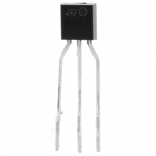
The 2STL1360 is an NPN bipolar junction transistor manufactured by STMicroelectronics, designed for general-purpose switching and amplification applications. This device features a maximum collector current of 3 A, collector-emitter breakdown voltage of 60 V, and maximum power dissipation of 1.2 W in a Through Hole TO-92L package. The 2STL1360 is classified as obsolete, making identification of functionally equivalent alternatives necessary for ongoing design support and component procurement.
Substiute Parts
Key Parameters
| Parameter | Value | Unit |
|---|---|---|
| Transistor Type | NPN | — |
| Current - Collector (Ic) Max | 3 | A |
| Voltage - Collector Emitter Breakdown (Max) | 60 | V |
| Power - Max | 1.2 | W |
| Frequency - Transition | 130 | MHz |
| Vce Saturation (Max) | 500 | mV @ 150mA, 3A |
| DC Current Gain (hFE) Min | 160 | @ 1A, 2V |
| Mounting Type | Through Hole | — |
| Package / Case | TO-226-3, TO-92-3 Long Body | — |
| Operating Temperature (Max) | 150 | °C (TJ) |
| RoHS Status | ROHS3 Compliant | — |
Substitute Part Grouping Explanation
Substitution of the 2STL1360 is determined by matching critical electrical and mechanical parameters within allowable tolerances. The primary substitution criteria are:
Mandatory Matching Parameters:
- Transistor polarity: NPN
- Maximum collector current: 3 A (equal or greater)
- Maximum power dissipation: 1.2 W (equal or greater)
- Mounting type: Through Hole
- Package compatibility: TO-92 form factor or equivalent
Secondary Compatibility Parameters:
- Collector-emitter breakdown voltage: 60 V minimum (higher values acceptable for voltage-limited applications)
- Transition frequency: 130 MHz minimum (higher values acceptable)
- DC current gain (hFE): 160 minimum at specified conditions (higher values acceptable)
- Operating temperature range: Must accommodate application requirements
The ZTX857 from Diodes Incorporated meets the mandatory matching criteria with equivalent collector current (3 A) and power rating (1.2 W) in a TO-92 compatible E-Line package. The ZTX857 exceeds the 2STL1360 in collector-emitter breakdown voltage (300 V vs. 60 V), making it suitable for applications requiring higher voltage headroom.
Parameter Comparison
| Parameter | 2STL1360 (STMicroelectronics) | ZTX857 (Diodes Incorporated) | Unit |
|---|---|---|---|
| Transistor Type | NPN | NPN | — |
| Current - Collector (Ic) Max | 3 | 3 | A |
| Voltage - Collector Emitter Breakdown (Max) | 60 | 300 | V |
| Power - Max | 1.2 | 1.2 | W |
| Frequency - Transition | 130 | 80 | MHz |
| Vce Saturation (Max) | 500 @ 150mA, 3A | 250 @ 600mA, 3A | mV |
| DC Current Gain (hFE) Min | 160 @ 1A, 2V | 100 @ 500mA, 10V | — |
| Current - Collector Cutoff (Max) | 100 | 50 | nA (ICBO) |
| Mounting Type | Through Hole | Through Hole | — |
| Package / Case | TO-226-3, TO-92-3 Long Body | E-Line-3 (TO-92 compatible) | — |
| Operating Temperature (Max) | 150 | 200 | °C (TJ) |
| Product Status | Obsolete | Active | — |
| RoHS Status | ROHS3 Compliant | ROHS3 Compliant | — |
Engineering Selection Recommendations
The ZTX857 is an active, in-stock substitute for the obsolete 2STL1360. Both devices are ROHS3 compliant and carry equivalent regulatory status (EAR99, REACH Unaffected). The ZTX857 maintains identical maximum collector current (3 A) and power dissipation (1.2 W), ensuring compatibility with existing circuit designs operating within the 2STL1360's original voltage and current specifications.
The ZTX857 provides enhanced voltage capability (300 V vs. 60 V), allowing use in higher-voltage applications without circuit modification. The E-Line package is mechanically compatible with TO-92 footprints, supporting direct board-level substitution. The ZTX857's lower transition frequency (80 MHz vs. 130 MHz) and reduced DC current gain (100 vs. 160 minimum) are acceptable for low-frequency switching applications but require verification for high-speed circuit designs.
The ZTX857's extended operating temperature range (−55°C to 200°C vs. 0°C to 150°C) and improved saturation characteristics (250 mV vs. 500 mV) provide additional design margin in thermal and switching-loss-sensitive applications.
Frequently Asked Questions (FAQ)
Q: Can the ZTX857 directly replace the 2STL1360 in existing designs?
A: Yes, for applications operating within the 2STL1360's original specifications (60 V maximum, 3 A maximum collector current, 1.2 W maximum power). The ZTX857 is mechanically compatible with TO-92 footprints and electrically compatible for these operating conditions. Circuit verification is required for designs utilizing the 2STL1360's transition frequency specification (130 MHz), as the ZTX857 operates at 80 MHz.
Q: What are the key differences between these devices?
A: The primary differences are collector-emitter breakdown voltage (60 V vs. 300 V), transition frequency (130 MHz vs. 80 MHz), and DC current gain (160 vs. 100 minimum). The ZTX857 offers higher voltage capability and extended temperature range, while the 2STL1360 provides higher frequency response and current gain. Both devices share identical maximum collector current and power dissipation ratings.
Q: Is the ZTX857 package compatible with the 2STL1360 footprint?
A: Yes. The ZTX857 E-Line package is mechanically compatible with TO-92 footprints. The 2STL1360 uses TO-92-3 Long Body packaging, and the ZTX857 E-Line-3 package maintains equivalent lead spacing and pin configuration for direct board-level substitution.
Q: Are both devices RoHS compliant?
A: Yes. Both the 2STL1360 and ZTX857 are ROHS3 compliant and carry equivalent regulatory classifications (EAR99, REACH Unaffected).
Q: What applications are suitable for the ZTX857 as a 2STL1360 replacement?
A: The ZTX857 is suitable for low-frequency switching applications, general-purpose amplification, and circuits operating at collector currents up to 3 A and power dissipation up to 1.2 W. Applications requiring transition frequencies above 80 MHz require design verification. The ZTX857's enhanced voltage rating (300 V) supports use in higher-voltage switching circuits without modification.
Q: How do saturation characteristics affect substitution?
A: The ZTX857 exhibits lower saturation voltage (250 mV vs. 500 mV at specified conditions), resulting in reduced power dissipation during saturation. This characteristic is beneficial for switching applications and does not prevent substitution. Designs relying on specific saturation voltage values require circuit verification.
Alternative Parts

SJ6012L2TP
Littelfuse Inc.
6 Alternative Parts

JMK107BBJ476MA-RE
Taiyo Yuden
10 Alternative Parts

GMK107BBJ475MA-T
Taiyo Yuden
5 Alternative Parts
SJ6020N2ARP
Littelfuse Inc.
3 Alternative Parts
SJ6025R2ATP
Littelfuse Inc.
4 Alternative Parts

2474-05L
API Delevan Inc.
1 Alternative Parts

4590R-684K
API Delevan Inc.
1 Alternative Parts

CM6560R-334
API Delevan Inc.
1 Alternative Parts

CM6460-104
API Delevan Inc.
1 Alternative Parts

5526-12
API Delevan Inc.
1 Alternative Parts