


Request Quote
(Ships tomorrow)
2SC5242RTU Equivalent & Substitute Parts
Part Overview
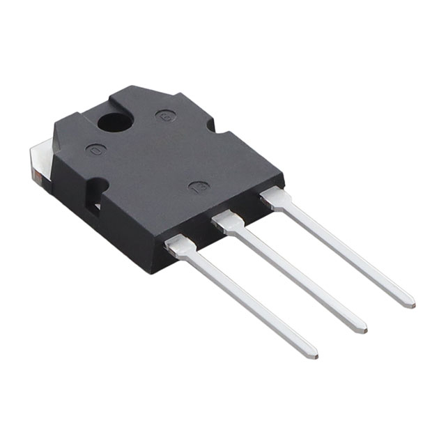
The 2SC5242RTU is an NPN bipolar junction transistor manufactured by onsemi, rated for 250 V collector-emitter breakdown voltage and 17 A maximum collector current. This through-hole TO-3P package device is designed for high-voltage, high-current switching and amplification applications with a maximum power dissipation of 130 W and transition frequency of 30 MHz.
The 2SC5242RTU is classified as obsolete. Equivalent and substitute parts are necessary to maintain design continuity, ensure supply chain availability, and support ongoing production requirements for applications utilizing this component.
Substiute Parts
Key Parameters
| Parameter | Value | Unit |
|---|---|---|
| Transistor Type | NPN | — |
| Voltage - Collector Emitter Breakdown (Max) | 250 | V |
| Current - Collector (Ic) (Max) | 17 | A |
| Power - Max | 130 | W |
| Frequency - Transition | 30 | MHz |
| Vce Saturation (Max) @ Ib, Ic | 3 V @ 800 mA, 8 A | — |
| DC Current Gain (hFE) (Min) @ Ic, Vce | 55 @ 1 A, 5 V | — |
| Current - Collector Cutoff (Max) | 5 | µA |
| Operating Temperature Range | −55 to 150 | °C |
| Mounting Type | Through Hole | — |
| Package / Case | TO-3P-3, SC-65-3 | — |
Substitute Part Grouping Explanation
Substitution of the 2SC5242RTU is determined by electrical and mechanical compatibility across the following critical parameters:
Electrical Compatibility Criteria:
- Transistor type (NPN)
- Collector-emitter breakdown voltage rating (minimum 250 V for direct substitution; lower ratings acceptable only if circuit design permits)
- Maximum collector current (minimum 17 A for direct substitution; higher ratings acceptable)
- Maximum power dissipation (minimum 130 W for direct substitution; higher ratings acceptable)
- Transition frequency (30 MHz minimum)
- Vce saturation characteristics
- DC current gain (hFE) characteristics
- Collector cutoff current (ICBO)
Mechanical Compatibility Criteria:
- Mounting type (Through Hole)
- Package / Case (TO-3P-3, SC-65-3)
Substitute parts identified below meet the electrical and mechanical requirements for direct replacement in applications designed for the 2SC5242RTU. Parts with reduced voltage or current ratings represent functional alternatives for circuits operating within their specified limits.
Parameter Comparison
| Parameter | 2SC5242RTU (Main) | 2SC5242-O(Q) | 2SC5200N(S1,E,S) |
|---|---|---|---|
| Manufacturer | onsemi | Toshiba Semiconductor and Storage | Toshiba Semiconductor and Storage |
| Transistor Type | NPN | NPN | NPN |
| Voltage - Collector Emitter Breakdown (Max) | 250 V | 230 V | 230 V |
| Current - Collector (Ic) (Max) | 17 A | 15 A | 15 A |
| Power - Max | 130 W | 130 W | 150 W |
| Frequency - Transition | 30 MHz | 30 MHz | 30 MHz |
| Vce Saturation (Max) @ Ib, Ic | 3 V @ 800 mA, 8 A | 3 V @ 800 mA, 8 A | 3 V @ 800 mA, 8 A |
| DC Current Gain (hFE) (Min) @ Ic, Vce | 55 @ 1 A, 5 V | 80 @ 1 A, 5 V | 80 @ 1 A, 5 V |
| Current - Collector Cutoff (Max) | 5 µA | 5 µA | 5 µA |
| Operating Temperature Range | −55 to 150 °C | 150 °C | 150 °C |
| Mounting Type | Through Hole | Through Hole | Through Hole |
| Package / Case | TO-3P-3, SC-65-3 | TO-3P-3, SC-65-3 | TO-3P-3, SC-65-3 |
| Product Status | Obsolete | Active | Active |
| RoHS Status | — | RoHS Compliant | ROHS3 Compliant |
Engineering Selection Recommendations
2SC5242-O(Q) (Toshiba Semiconductor and Storage)
The 2SC5242-O(Q) is an active product offering direct mechanical and functional compatibility with the 2SC5242RTU. Both devices share identical package specifications (TO-3P-3, SC-65-3) and transition frequency (30 MHz). The 2SC5242-O(Q) operates at reduced voltage (230 V versus 250 V) and current (15 A versus 17 A) ratings, with equivalent power dissipation (130 W). The higher DC current gain (80 versus 55 at 1 A, 5 V) provides improved base drive efficiency. This part is RoHS Compliant and suitable for applications where the reduced electrical ratings are acceptable. Inventory availability is 926 units.
2SC5200N(S1,E,S) (Toshiba Semiconductor and Storage)
The 2SC5200N(S1,E,S) is an active product with identical mechanical compatibility and transition frequency to the 2SC5242RTU. This device operates at reduced voltage (230 V) and current (15 A) ratings but provides higher maximum power dissipation (150 W). The DC current gain is higher (80 versus 55 at 1 A, 5 V). This part is ROHS3 Compliant and offers superior thermal performance. Inventory availability is 17,650 units, providing greater supply chain security.
Both substitute parts are active products with established supply chains, addressing the obsolescence status of the 2SC5242RTU. Selection between them depends on application-specific requirements regarding voltage headroom, current capacity, and thermal management needs.
Frequently Asked Questions (FAQ)
Q: Can the 2SC5242-O(Q) or 2SC5200N(S1,E,S) be used as direct replacements for the 2SC5242RTU?
A: Both parts are mechanically compatible (TO-3P package) and electrically compatible for applications operating within their specified voltage (230 V) and current (15 A) limits. The 2SC5242RTU is rated for 250 V and 17 A; applications requiring these higher ratings must evaluate circuit design margins before substitution.
Q: What is the difference between the 2SC5242-O(Q) and 2SC5200N(S1,E,S)?
A: Both parts share identical electrical ratings (230 V, 15 A, 30 MHz). The primary difference is maximum power dissipation: the 2SC5200N(S1,E,S) is rated for 150 W versus 130 W for the 2SC5242-O(Q). The 2SC5200N(S1,E,S) offers better thermal performance and higher inventory availability (17,650 units versus 926 units).
Q: Are there compliance differences between the substitute parts?
A: The 2SC5242-O(Q) is RoHS Compliant. The 2SC5200N(S1,E,S) is ROHS3 Compliant, representing a more recent environmental standard. Both parts are REACH Unaffected. Selection depends on specific regulatory requirements for the end application.
Q: What are the DC current gain differences, and do they affect substitution?
A: The 2SC5242RTU has a minimum DC current gain (hFE) of 55 at 1 A, 5 V. Both substitute parts have a minimum hFE of 80 at the same conditions. Higher current gain reduces base drive requirements and improves switching efficiency. This difference is beneficial for most applications.
Q: How do the operating temperature ranges compare?
A: The 2SC5242RTU operates from −55 to 150 °C. The substitute parts are specified to 150 °C maximum. Applications requiring operation below 0 °C must confirm the lower temperature limit of substitute parts or retain the original component.
Q: What packaging differences exist between these parts?
A: All three parts use identical TO-3P-3 and SC-65-3 package specifications and through-hole mounting. No mechanical redesign is required for substitution.
Alternative Parts

SJ6012L2TP
Littelfuse Inc.
6 Alternative Parts

JMK107BBJ476MA-RE
Taiyo Yuden
10 Alternative Parts

GMK107BBJ475MA-T
Taiyo Yuden
5 Alternative Parts
SJ6020N2ARP
Littelfuse Inc.
3 Alternative Parts
SJ6025R2ATP
Littelfuse Inc.
4 Alternative Parts

2474-05L
API Delevan Inc.
1 Alternative Parts

4590R-684K
API Delevan Inc.
1 Alternative Parts

CM6560R-334
API Delevan Inc.
1 Alternative Parts

CM6460-104
API Delevan Inc.
1 Alternative Parts

5526-12
API Delevan Inc.
1 Alternative Parts