


Request Quote
(Ships tomorrow)
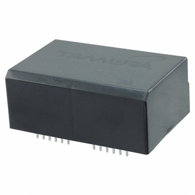
2DM180506CM Half-Bridge Gate Driver IC Equivalent & Substitute Parts
Part Overview
The 2DM180506CM is a half-bridge gate driver IC manufactured by Tamura, designed for driving N-Channel MOSFETs in half-bridge configurations. This component operates with a supply voltage range of 15V to 24V and features independent dual-channel architecture with logic voltage thresholds of 0.8V (VIL) and 2V (VIH). The device is packaged in a 34-DIP Module with 31 leads and is mounted through-hole.
The 2DM180506CM is classified as obsolete. Identifying equivalent substitute parts is necessary to maintain design continuity, ensure supply chain reliability, and support ongoing production requirements for applications utilizing this gate driver topology.
Substiute Parts
Key Parameters
| Parameter | Value |
|---|---|
| Manufacturer Part Number | 2DM180506CM |
| Manufacturer | Tamura |
| Category | Power Management (PMIC) |
| Driven Configuration | Half-Bridge |
| Number of Drivers | 2 |
| Gate Type | N-Channel MOSFET |
| Voltage - Supply | 15V ~ 24V |
| Logic Voltage - VIL, VIH | 0.8V, 2V |
| Operating Temperature | -30°C ~ 85°C (TA) |
| Mounting Type | Through Hole |
| Package / Case | 34-DIP Module, 31 Leads |
| Product Status | Obsolete |
| RoHS Status | RoHS Compliant |
Substitute Part Grouping Explanation
Substitution of the 2DM180506CM is determined by the following critical parameters:
Functional Architecture: Half-bridge configuration with independent dual-channel drivers is mandatory. The substitute must maintain this topology to ensure compatibility with existing circuit designs.
Gate Driver Capability: The original part drives N-Channel MOSFETs. Substitute parts must support equivalent or expanded gate driver capabilities (N-Channel MOSFET, IGBT, or SiC MOSFET support indicates broader compatibility).
Supply Voltage Range: The original operates at 15V to 24V. Substitute parts must have a supply voltage range that encompasses or exceeds this specification to ensure proper operation across the intended application envelope.
Logic Voltage Thresholds: Input logic levels (VIL, VIH) define signal interpretation. Substitute parts with different logic voltage specifications may require circuit redesign and are evaluated based on application requirements.
Operating Temperature Range: The original operates from -30°C to 85°C. Substitute parts with equal or extended temperature ranges maintain thermal performance requirements.
Mounting and Packaging: Through-hole mounting is specified for the original. Substitute parts must maintain through-hole mounting compatibility unless circuit board redesign is acceptable.
Compliance and Status: Active product status and current compliance certifications (RoHS3, REACH) indicate ongoing manufacturer support and regulatory alignment.
Parameter Comparison
| Parameter | 2DM180506CM (Original) | 2CG010BBC13N (Substitute) |
|---|---|---|
| Manufacturer | Tamura | Tamura |
| Category | Power Management (PMIC) | Power Management (PMIC) |
| Driven Configuration | Half-Bridge | Half-Bridge |
| Channel Type | Independent | Independent |
| Number of Drivers | 2 | 2 |
| Gate Type | N-Channel MOSFET | IGBT, SiC MOSFET |
| Voltage - Supply | 15V ~ 24V | 13V ~ 28V |
| Logic Voltage - VIL, VIH | 0.8V, 2V | 1.65V, 3.85V |
| Current - Peak Output (Source, Sink) | Not Specified | 43A, 43A |
| Operating Temperature | -30°C ~ 85°C (TA) | -40°C ~ 85°C (TA) |
| Mounting Type | Through Hole | Through Hole |
| Package / Case | 34-DIP Module, 31 Leads | Module |
| Product Status | Obsolete | Active |
| RoHS Status | RoHS Compliant | ROHS3 Compliant |
Engineering Selection Recommendations
The 2CG010BBC13N is identified as a functional substitute for the 2DM180506CM based on the following engineering criteria:
Topology Compatibility: Both devices implement half-bridge gate driver architecture with independent dual-channel configuration, ensuring functional equivalence in half-bridge switching applications.
Supply Voltage Envelope: The 2CG010BBC13N supply range of 13V to 28V encompasses the original 15V to 24V specification, providing operational compatibility across the intended voltage envelope with extended margin.
Gate Driver Capability: The 2CG010BBC13N supports IGBT and SiC MOSFET gate driving in addition to N-Channel MOSFET support, providing expanded device compatibility compared to the original N-Channel MOSFET-only specification.
Output Current Specification: The 2CG010BBC13N provides specified peak output current of 43A (source and sink), whereas the original part does not specify this parameter. This additional capability supports higher switching frequency and lower impedance load applications.
Temperature Range Extension: The 2CG010BBC13N operating range of -40°C to 85°C extends the lower temperature limit by 10°C compared to the original -30°C specification, supporting broader thermal application requirements.
Product Status and Compliance: The 2CG010BBC13N is classified as active with ROHS3 compliance and REACH unaffected status, ensuring ongoing manufacturer support, regulatory alignment, and supply chain availability.
Logic Voltage Consideration: The 2CG010BBC13N logic voltage thresholds (VIL 1.65V, VIH 3.85V) differ from the original (VIL 0.8V, VIH 2V). Circuit input signal conditioning must be verified to ensure compatibility with the higher logic voltage thresholds.
Frequently Asked Questions (FAQ)
Q: Can the 2CG010BBC13N directly replace the 2DM180506CM without circuit modifications?
A: The 2CG010BBC13N maintains half-bridge topology, independent dual-channel architecture, and through-hole mounting compatibility. However, the logic voltage thresholds differ (1.65V/3.85V versus 0.8V/2V). Input signal conditioning circuits must be evaluated to ensure the control signal levels meet the 2CG010BBC13N specifications. Package form factor differences may also require mechanical verification.
Q: What is the significance of the extended supply voltage range in the 2CG010BBC13N?
A: The 2CG010BBC13N operates from 13V to 28V compared to the original 15V to 24V range. This extended range provides operational margin at lower supply voltages (13V to 15V) and higher supply voltages (24V to 28V). Applications operating at the extremes of the original specification benefit from this extended envelope.
Q: How do the peak output current specifications affect substitution?
A: The 2CG010BBC13N specifies 43A peak output current (source and sink), while the original does not provide this specification. Higher output current capability supports faster switching transitions, lower gate impedance, and higher frequency operation. Applications with marginal gate drive current in the original design may benefit from this increased capability.
Q: Are there packaging considerations for substitution?
A: The original 2DM180506CM uses a 34-DIP Module with 31 leads. The 2CG010BBC13N is specified as a Module package. Physical dimensions, pin configuration, and PCB footprint must be verified to ensure mechanical compatibility. Through-hole mounting is maintained in both devices.
Q: What compliance certifications should be verified for the substitute part?
A: The 2CG010BBC13N carries ROHS3 compliance and REACH unaffected status, compared to the original RoHS Compliant designation. For applications requiring specific regulatory compliance, these certifications should be cross-referenced with application requirements. The substitute part meets current regulatory standards.
Q: How does the operating temperature range affect application suitability?
A: The 2CG010BBC13N extends the lower operating temperature to -40°C compared to the original -30°C. Both maintain the upper limit of 85°C. Applications operating in cold environments benefit from the extended lower temperature specification. Thermal management and derating curves should be reviewed for the specific application.
Alternative Parts

SJ6012L2TP
Littelfuse Inc.
6 Alternative Parts

JMK107BBJ476MA-RE
Taiyo Yuden
10 Alternative Parts

GMK107BBJ475MA-T
Taiyo Yuden
5 Alternative Parts
SJ6020N2ARP
Littelfuse Inc.
3 Alternative Parts
SJ6025R2ATP
Littelfuse Inc.
4 Alternative Parts

2474-05L
API Delevan Inc.
1 Alternative Parts

4590R-684K
API Delevan Inc.
1 Alternative Parts

CM6560R-334
API Delevan Inc.
1 Alternative Parts

CM6460-104
API Delevan Inc.
1 Alternative Parts

5526-12
API Delevan Inc.
1 Alternative Parts