


Request Quote
(Ships tomorrow)
1008HC-183EKFS Equivalent & Substitute Parts Reference
Part Overview
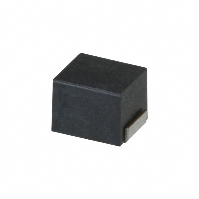
The 1008HC-183EKFS is a fixed inductance surface mount component manufactured by Delta Electronics/Components. This 18 µH unshielded drum core wirewound inductor is rated for 200 mA continuous current with a DC resistance of 2.6 Ohm and operates across the temperature range of -40°C to 85°C. The component is classified as obsolete, necessitating identification of active equivalent alternatives that maintain functional compatibility for new designs and production continuity.
Substiute Parts
Key Parameters
| Parameter | Value |
|---|---|
| Inductance | 18 µH |
| Current Rating | 200 mA |
| DC Resistance (DCR) | 2.6 Ohm |
| Core Type | Ferrite Drum Core, Unshielded |
| Mounting Type | Surface Mount |
| Package | 1008 (2520 Metric) |
| Operating Temperature Range | -40°C to 85°C |
| Inductance Tolerance | ±10% |
| Q Factor @ 2.52 MHz | 20 |
| Self Resonant Frequency | 20 MHz |
| RoHS Status | ROHS3 Compliant |
| Moisture Sensitivity Level | 1 (Unlimited) |
Substitute Part Grouping Explanation
Substitution of the 1008HC-183EKFS is determined by strict alignment of the following electrical and mechanical parameters:
Primary Substitution Criteria:
- Inductance value: 18 µH (exact match required)
- Package designation: 1008 (2520 Metric) surface mount form factor
- Core material: Ferrite drum core, unshielded construction
- Mounting type: Surface mount technology
Secondary Compatibility Parameters:
- Current rating must equal or exceed 200 mA minimum requirement
- DC resistance must not exceed design circuit specifications
- Operating temperature range must encompass -40°C to 85°C minimum
- Inductance tolerance and Q factor must support circuit performance requirements
- RoHS3 compliance and MSL 1 rating required for manufacturing compatibility
The NLV25T-180J-EF from TDK Corporation meets the primary substitution criteria with identical inductance and package specifications. However, secondary parameters show trade-offs that must be evaluated for specific circuit applications.
Parameter Comparison
| Parameter | 1008HC-183EKFS (Delta) | NLV25T-180J-EF (TDK) | Compatibility Notes |
|---|---|---|---|
| Inductance | 18 µH | 18 µH | Exact match |
| Inductance Tolerance | ±10% | ±5% | TDK offers tighter tolerance |
| Current Rating (Amps) | 200 mA | 130 mA | Delta rated higher; TDK lower by 70 mA |
| DC Resistance (DCR) | 2.6 Ohm | 4.8 Ohm Max | Delta lower; TDK higher by 2.2 Ohm |
| Q @ 2.52 MHz | 20 | 25 | TDK higher Q factor |
| Self Resonant Frequency | 20 MHz | 24 MHz | TDK higher SRF |
| Operating Temperature Range | -40°C to 85°C | -40°C to 105°C | TDK extended upper limit |
| Package / Case | 1008 (2520 Metric) | 1008 (2520 Metric) | Exact match |
| Size / Dimension | 0.115" L x 0.110" W (2.92mm x 2.79mm) | 0.098" L x 0.079" W (2.50mm x 2.00mm) | TDK physically smaller |
| Height - Seated (Max) | 0.083" (2.10mm) | 0.075" (1.90mm) | TDK lower profile |
| RoHS Status | ROHS3 Compliant | ROHS3 Compliant | Both compliant |
| Moisture Sensitivity Level | 1 (Unlimited) | 1 (Unlimited) | Both MSL 1 |
| Product Status | Obsolete | Active | TDK actively manufactured |
Engineering Selection Recommendations
Substitution Feasibility:
The NLV25T-180J-EF is a functional equivalent for the 1008HC-183EKFS based on matching inductance value, package form factor, and core construction. Both components are ROHS3 compliant with MSL 1 rating, ensuring manufacturing process compatibility.
Critical Design Considerations:
The NLV25T-180J-EF exhibits a reduced current rating of 130 mA compared to the original 200 mA specification. This substitution is suitable only for circuits where the actual operating current does not exceed 130 mA. Circuits designed for the full 200 mA capability of the 1008HC-183EKFS cannot use the TDK substitute without thermal and saturation analysis.
The DC resistance differential of 2.2 Ohm (Delta 2.6 Ohm versus TDK 4.8 Ohm maximum) introduces increased power dissipation in the TDK component. For applications sensitive to inductor losses, this parameter shift must be evaluated against circuit performance requirements.
Advantages of NLV25T-180J-EF:
- Active product status ensures long-term availability and supply chain continuity
- Extended operating temperature range (-40°C to 105°C) provides thermal margin
- Tighter inductance tolerance (±5%) supports precision circuit requirements
- Higher Q factor (25 versus 20) indicates lower losses at 2.52 MHz
- Higher self-resonant frequency (24 MHz) extends usable frequency range
- Physically smaller footprint reduces PCB space requirements
Limitations of NLV25T-180J-EF:
- Current rating 70 mA lower than original specification
- Maximum DC resistance 2.2 Ohm higher than original specification
- Substitution requires verification that circuit current does not exceed 130 mA
Frequently Asked Questions (FAQ)
Q: Can the NLV25T-180J-EF directly replace the 1008HC-183EKFS in all applications?
A: Direct replacement is possible only when circuit operating current remains below 130 mA. The TDK component has a lower current rating (130 mA versus 200 mA). Applications requiring the full 200 mA capability require alternative solutions or thermal analysis to confirm the TDK component operates within safe limits.
Q: What is the impact of the higher DC resistance in the NLV25T-180J-EF?
A: The TDK component has a maximum DC resistance of 4.8 Ohm compared to 2.6 Ohm in the Delta original. This increases power dissipation by approximately 2.2 Ohm × I² watts. For a 100 mA circuit, this represents an additional 22 mW of dissipation. Circuit thermal design must accommodate this increase.
Q: Are both components physically compatible with the same PCB footprint?
A: Both components use the 1008 (2520 Metric) package designation. However, the NLV25T-180J-EF is physically smaller (2.50mm × 2.00mm versus 2.92mm × 2.79mm) with lower height (1.90mm versus 2.10mm). The smaller TDK component will fit within the original footprint with clearance margin, ensuring PCB compatibility.
Q: What is the significance of the different inductance tolerances?
A: The NLV25T-180J-EF offers ±5% tolerance compared to ±10% for the original. This tighter tolerance reduces inductance variation across production batches, beneficial for precision circuits. However, this does not affect substitution feasibility; it represents an improvement in component consistency.
Q: Why does the TDK component have a higher operating temperature maximum?
A: The NLV25T-180J-EF is rated to 105°C versus 85°C for the Delta component. This extended range provides additional thermal margin in high-temperature environments but does not affect substitution for applications operating within the original -40°C to 85°C range.
Q: Are there any compliance or certification differences between the two components?
A: Both components are ROHS3 compliant with MSL 1 rating. The Delta component is REACH Unaffected while the TDK component is REACH Affected. Both carry EAR99 ECCN classification. For applications subject to REACH regulations, the TDK component requires compliance verification with supply chain documentation.
Q: What packaging format is available for the NLV25T-180J-EF?
A: The NLV25T-180J-EF is supplied in Tape & Reel (TR) format, standard for high-volume surface mount assembly. The original 1008HC-183EKFS packaging format is not specified in the provided data. Verify packaging compatibility with assembly equipment and procurement requirements.
Alternative Parts

SJ6012L2TP
Littelfuse Inc.
6 Alternative Parts

JMK107BBJ476MA-RE
Taiyo Yuden
10 Alternative Parts

GMK107BBJ475MA-T
Taiyo Yuden
5 Alternative Parts
SJ6020N2ARP
Littelfuse Inc.
3 Alternative Parts
SJ6025R2ATP
Littelfuse Inc.
4 Alternative Parts

2474-05L
API Delevan Inc.
1 Alternative Parts

4590R-684K
API Delevan Inc.
1 Alternative Parts

CM6560R-334
API Delevan Inc.
1 Alternative Parts

CM6460-104
API Delevan Inc.
1 Alternative Parts

5526-12
API Delevan Inc.
1 Alternative Parts