


Request Quote
(Ships tomorrow)
Equivalent & Substitute Parts for 0410CDMCCDS-2R2MC
Part Overview
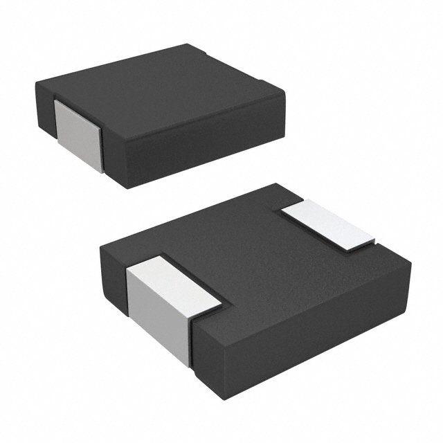
The 0410CDMCCDS-2R2MC is a 2.2 µH shielded molded inductor manufactured by Sumida America Components Inc., designed for surface mount applications with a current rating of 2.9 A and maximum DC resistance of 107mOhm. This component is classified as Active product status and is suitable for high-frequency filtering, energy storage, and signal conditioning circuits operating within the -55°C to 125°C temperature range.
Substitute parts become necessary when the original manufacturer part experiences extended lead times, inventory constraints, or when design requirements permit operation within alternative electrical and mechanical specifications. The substitute parts listed maintain the core functional parameters of 2.2 µH inductance and ±20% tolerance while offering variations in current handling capacity and DC resistance characteristics.
Substiute Parts
Key Parameters
| Parameter | Value | Unit | Significance for Substitution |
|---|---|---|---|
| Inductance | 2.2 | µH | Core functional specification; must match exactly |
| Inductance Tolerance | ±20% | % | Acceptable variation range; must be equal or tighter |
| Current Rating | 2.9 | A | Minimum acceptable current handling; substitutes must meet or exceed |
| DC Resistance (DCR) | 107 | mOhm Max | Power loss parameter; lower values indicate improved performance |
| Shielding | Shielded | — | Electromagnetic interference containment; must be maintained |
| Operating Temperature | -55 to 125 | °C | Thermal operating range; must be equal or wider |
| Mounting Type | Surface Mount | — | Assembly compatibility; must remain surface mount |
| Package Type | Nonstandard | — | Physical form factor; dimensional compatibility required |
Substitute Part Grouping Explanation
Substitution eligibility for the 0410CDMCCDS-2R2MC is determined by strict adherence to the following electrical and mechanical parameters:
Mandatory Matching Parameters:
- Inductance value: 2.2 µH (exact match required)
- Inductance tolerance: ±20% (equal or tighter tolerance acceptable)
- Shielding type: Shielded (electromagnetic containment requirement)
- Operating temperature range: -55°C to 125°C (equal or wider range acceptable)
- Mounting type: Surface Mount (assembly process compatibility)
Performance Enhancement Parameters (Substitutes May Exceed):
- Current Rating (Amps): Substitute must equal or exceed 2.9 A
- DC Resistance (DCR): Lower values acceptable; reduces power dissipation
- Current Saturation (Isat): Higher values acceptable; improves headroom
Dimensional Compatibility:
- Physical size and height must accommodate existing PCB layout and assembly constraints
The two substitute parts listed—IHLP1616ABER2R2M11 and IHLP1616BZER2R2M11—both satisfy all mandatory matching parameters while offering improved current handling and reduced DC resistance characteristics.
Parameter Comparison
| Parameter | 0410CDMCCDS-2R2MC (Main) | IHLP1616ABER2R2M11 | IHLP1616BZER2R2M11 |
|---|---|---|---|
| Manufacturer | Sumida America Components Inc. | Vishay Dale | Vishay Dale |
| Inductance | 2.2 µH | 2.2 µH | 2.2 µH |
| Inductance Tolerance | ±20% | ±20% | ±20% |
| Current Rating | 2.9 A | 2.75 A | 3.25 A |
| Current Saturation (Isat) | 3.1 A | 3.0 A | 3.25 A |
| DC Resistance (DCR) | 107 mOhm Max | 83.5 mOhm Max | 68 mOhm Max |
| Shielding | Shielded | Shielded | Shielded |
| Operating Temperature | -55°C to 125°C | -55°C to 125°C | -55°C to 125°C |
| Inductance Test Frequency | 100 kHz | 100 kHz | 100 kHz |
| Mounting Type | Surface Mount | Surface Mount | Surface Mount |
| Package / Case | Nonstandard | Nonstandard | Nonstandard |
| Size / Dimension | 4.40mm L x 4.20mm W | 4.45mm L x 4.06mm W | 4.45mm L x 4.06mm W |
| Height - Seated (Max) | 1.00 mm | 1.20 mm | 2.00 mm |
| Moisture Sensitivity Level (MSL) | 1 (Unlimited) | 1 (Unlimited) | 1 (Unlimited) |
| Product Status | Active | Active | Active |
| RoHS Status | — | ROHS3 Compliant | ROHS3 Compliant |
| REACH Status | — | REACH Unaffected | REACH Unaffected |
Engineering Selection Recommendations
IHLP1616ABER2R2M11 Selection Criteria:
This substitute is suitable when current requirements are within 2.75 A and space constraints permit a maximum seated height of 1.20 mm. The 83.5 mOhm DC resistance provides improved efficiency compared to the main part, reducing thermal dissipation by approximately 22%. This part maintains full compliance with ROHS3 and REACH regulations. Inventory availability of 35,400 pieces supports production continuity.
IHLP1616BZER2R2M11 Selection Criteria:
This substitute is optimal for applications requiring maximum current headroom, with a 3.25 A rating matching the saturation current specification. The 68 mOhm DC resistance delivers the lowest power loss among all options, reducing thermal dissipation by approximately 36% relative to the main part. However, the 2.00 mm maximum seated height requires verification against PCB assembly clearance constraints. This part is ROHS3 compliant and REACH unaffected. Inventory availability of 15,778 pieces supports standard production volumes.
Dimensional Compatibility Assessment:
The main part measures 4.40mm L x 4.20mm W x 1.00mm H. Both substitute parts measure 4.45mm L x 4.06mm W, representing minimal lateral dimensional variation (0.05mm length increase, 0.14mm width decrease). Height differences are more significant: IHLP1616ABER2R2M11 at 1.20 mm and IHLP1616BZER2R2M11 at 2.00 mm. PCB layout verification is required to confirm clearance compatibility, particularly for the taller IHLP1616BZER2R2M11 variant.
Frequently Asked Questions (FAQ)
Q: Can IHLP1616ABER2R2M11 be used as a direct replacement for 0410CDMCCDS-2R2MC?
A: Yes, with dimensional verification. The IHLP1616ABER2R2M11 meets all mandatory electrical parameters: 2.2 µH inductance, ±20% tolerance, shielded construction, and -55°C to 125°C operating range. The 2.75 A current rating is slightly below the main part's 2.9 A specification; applications operating above 2.75 A require the IHLP1616BZER2R2M11. The 1.20 mm seated height requires PCB clearance confirmation.
Q: What is the advantage of IHLP1616BZER2R2M11 over the main part?
A: The IHLP1616BZER2R2M11 provides three performance improvements: (1) higher current rating of 3.25 A versus 2.9 A, providing 12% additional headroom; (2) reduced DC resistance of 68 mOhm versus 107 mOhm, decreasing power dissipation by 36%; (3) higher saturation current of 3.25 A matching the current rating. The trade-off is increased seated height of 2.00 mm, requiring PCB assembly space verification.
Q: Are the substitute parts compatible with existing PCB layouts designed for 0410CDMCCDS-2R2MC?
A: Lateral dimensions are nearly identical (4.40-4.45mm length, 4.06-4.20mm width), ensuring footprint compatibility. However, height differences must be evaluated: the main part is 1.00 mm tall, IHLP1616ABER2R2M11 is 1.20 mm, and IHLP1616BZER2R2M11 is 2.00 mm. Applications with tight vertical clearance constraints may require layout modification or selection of the lower-profile IHLP1616ABER2R2M11.
Q: Do the substitute parts meet the same regulatory compliance as the main part?
A: The substitute parts exceed the main part's compliance profile. Both IHLP1616ABER2R2M11 and IHLP1616BZER2R2M11 are ROHS3 compliant and REACH unaffected. The main part's compliance status for these regulations is not specified in the provided data. Both substitutes maintain EAR99 export classification and 8504.50.4000 HTSUS code alignment.
Q: What is the DC resistance impact on circuit performance?
A: DC resistance directly affects power dissipation and thermal performance. The main part's 107 mOhm DCR dissipates approximately 0.70 W at 2.9 A continuous current. IHLP1616ABER2R2M11 at 83.5 mOhm dissipates 0.56 W at 2.75 A (22% reduction). IHLP1616BZER2R2M11 at 68 mOhm dissipates 0.72 W at 3.25 A (36% reduction at rated current). Lower DCR reduces thermal stress and extends component lifespan in thermally constrained applications.
Q: Can both substitute parts be used interchangeably in the same design?
A: Interchangeability depends on application requirements. If the circuit operates below 2.75 A and space permits 1.20 mm height, IHLP1616ABER2R2M11 is suitable. If current approaches or exceeds 2.75 A, or if maximum efficiency is required, IHLP1616BZER2R2M11 is necessary. Both parts are electrically compatible with the main part's 2.2 µH inductance and ±20% tolerance specification, but physical height differences may prevent mechanical interchangeability on the same PCB.
Q: What is the self-resonant frequency significance?
A: IHLP1616ABER2R2M11 has a self-resonant frequency of 49 MHz, while IHLP1616BZER2R2M11 is 40 MHz. The main part's self-resonant frequency is not specified. Self-resonant frequency defines the upper frequency limit where the inductor behaves as a pure inductance; above this frequency, parasitic capacitance dominates. For applications operating below 40 MHz, both substitutes are suitable. Applications requiring operation near or above 40 MHz should select IHLP1616ABER2R2M11 for higher resonant frequency margin.
Alternative Parts

SJ6012L2TP
Littelfuse Inc.
6 Alternative Parts

JMK107BBJ476MA-RE
Taiyo Yuden
10 Alternative Parts

GMK107BBJ475MA-T
Taiyo Yuden
5 Alternative Parts
SJ6020N2ARP
Littelfuse Inc.
3 Alternative Parts
SJ6025R2ATP
Littelfuse Inc.
4 Alternative Parts

2474-05L
API Delevan Inc.
1 Alternative Parts

4590R-684K
API Delevan Inc.
1 Alternative Parts

CM6560R-334
API Delevan Inc.
1 Alternative Parts

CM6460-104
API Delevan Inc.
1 Alternative Parts

5526-12
API Delevan Inc.
1 Alternative Parts