


Request Quote
(Ships tomorrow)
0410CDMCBDS-2R2MC Equivalent & Substitute Parts
Part Overview
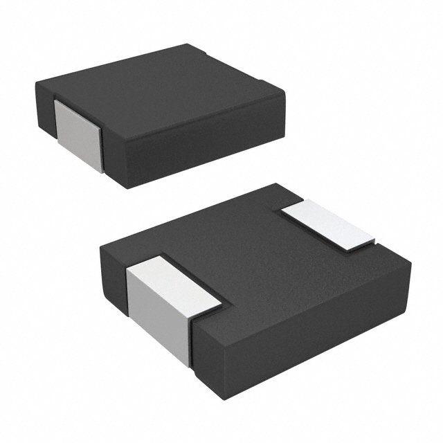
The 0410CDMCBDS-2R2MC is a 2.2 µH shielded wirewound inductor manufactured by Sumida America Components Inc., rated for 2.6 A continuous current with 104mOhm DC resistance. This component is classified as obsolete, making identification of equivalent substitute parts essential for ongoing design support and procurement continuity. The part is surface-mounted in a 2-SMD package measuring 4.50mm × 4.10mm with a maximum seated height of 1.20mm, operating across the temperature range of -40°C to 105°C.
Substiute Parts
Key Parameters
| Parameter | Value | Unit |
|---|---|---|
| Inductance | 2.2 | µH |
| Inductance Tolerance | ±20% | — |
| Current Rating | 2.6 | A |
| DC Resistance (DCR) | 104 | mOhm |
| Saturation Current (Isat) | 2 | A |
| Shielding | Shielded | — |
| Mounting Type | Surface Mount | — |
| Package Type | 2-SMD | — |
| Operating Temperature Range | -40°C to 105°C | — |
| RoHS Status | ROHS3 Compliant | — |
Substitute Part Grouping Explanation
Substitution of the 0410CDMCBDS-2R2MC is determined by strict equivalence across the following critical parameters:
Primary Matching Criteria:
- Inductance value: 2.2 µH (fixed)
- Inductance tolerance: ±20% (fixed)
- Shielding requirement: Shielded (mandatory for EMI performance)
- Mounting technology: Surface Mount (fixed)
- Inductance test frequency: 100 kHz (fixed)
- RoHS compliance: ROHS3 Compliant (regulatory requirement)
- Moisture sensitivity: MSL 1 (Unlimited)
Secondary Compatibility Parameters:
- Current rating: Substitute must equal or exceed 2.6 A
- DC resistance: Substitute must not exceed 104mOhm (lower values acceptable)
- Operating temperature range: Substitute must cover or exceed -40°C to 105°C
- Physical dimensions: Substitute must fit within or match PCB footprint constraints
The IHLP1616BZER2R2M01 from Vishay Dale meets all primary matching criteria and exceeds secondary compatibility requirements.
Parameter Comparison
| Parameter | 0410CDMCBDS-2R2MC (Main) | IHLP1616BZER2R2M01 (Substitute) | Compatibility |
|---|---|---|---|
| Manufacturer | Sumida America Components Inc. | Vishay Dale | Different manufacturer |
| Inductance | 2.2 µH | 2.2 µH | Equivalent |
| Inductance Tolerance | ±20% | ±20% | Equivalent |
| Current Rating | 2.6 A | 2.85 A | Substitute exceeds requirement |
| Saturation Current (Isat) | 2 A | 6 A | Substitute exceeds requirement |
| DC Resistance (DCR) | 104 mOhm | 90 mOhm Max | Substitute is superior |
| Shielding | Shielded | Shielded | Equivalent |
| Type | Wirewound | Molded | Different construction |
| Operating Temperature | -40°C to 105°C | -55°C to 125°C | Substitute exceeds range |
| Inductance Test Frequency | 100 kHz | 100 kHz | Equivalent |
| Mounting Type | Surface Mount | Surface Mount | Equivalent |
| Package / Case | 2-SMD | Nonstandard | Different package designation |
| Size / Dimension | 4.50mm L × 4.10mm W | 4.45mm L × 4.06mm W | Physically compatible |
| Height - Seated (Max) | 1.20 mm | 2.00 mm | Substitute is taller |
| RoHS Status | ROHS3 Compliant | ROHS3 Compliant | Equivalent |
| Moisture Sensitivity Level | MSL 1 (Unlimited) | MSL 1 (Unlimited) | Equivalent |
| Product Status | Obsolete | Active | Substitute is in production |
Engineering Selection Recommendations
The IHLP1616BZER2R2M01 is a direct functional substitute for the obsolete 0410CDMCBDS-2R2MC based on the following engineering criteria:
Electrical Equivalence: Both inductors provide 2.2 µH inductance at 100 kHz with ±20% tolerance. The substitute delivers superior electrical performance with lower DC resistance (90mOhm vs. 104mOhm) and higher current ratings (2.85 A vs. 2.6 A), providing design margin for thermal and saturation performance.
Compliance & Certification: Both parts are ROHS3 compliant and carry MSL 1 (Unlimited) moisture sensitivity ratings, meeting regulatory and manufacturing requirements without additional qualification.
Product Availability: The main part is obsolete with limited remaining inventory (788 pcs). The substitute is active in production with substantial inventory availability (36,620 pcs), ensuring long-term procurement continuity.
Physical Considerations: The substitute maintains compatible footprint dimensions (4.45mm × 4.06mm vs. 4.50mm × 4.10mm). The increased seated height (2.00mm vs. 1.20mm) requires verification against PCB clearance constraints and component stacking requirements in the target application.
Temperature Performance: The substitute operates across -55°C to 125°C, exceeding the original part's -40°C to 105°C range and providing enhanced thermal margin for extended operating conditions.
Frequently Asked Questions (FAQ)
Q: Can the IHLP1616BZER2R2M01 directly replace the 0410CDMCBDS-2R2MC without circuit modification?
A: Electrical substitution is direct. The inductance value, tolerance, and test frequency are identical. However, the increased seated height (2.00mm vs. 1.20mm) requires verification of PCB clearance and component placement constraints. No circuit modifications are necessary if physical space permits.
Q: What is the significance of the different inductor construction types (wirewound vs. molded)?
A: The main part uses wirewound construction; the substitute uses molded construction. Both are shielded and tested at 100 kHz. The molded design in the substitute provides improved saturation current (6A vs. 2A) and lower DC resistance (90mOhm vs. 104mOhm), resulting in superior thermal performance and reduced power dissipation.
Q: Does the lower DC resistance of the substitute affect circuit performance?
A: Lower DC resistance is beneficial. It reduces I²R losses and heat generation at the rated current of 2.6 A. The substitute's 90mOhm DCR is superior to the original 104mOhm specification, improving overall circuit efficiency without requiring design changes.
Q: Are there any thermal or reliability concerns with the substitute?
A: The substitute's extended operating temperature range (-55°C to 125°C vs. -40°C to 105°C) and higher saturation current (6A vs. 2A) indicate enhanced thermal stability and margin. Both parts carry identical MSL 1 ratings and ROHS3 compliance, indicating equivalent reliability profiles for moisture and environmental exposure.
Q: What should be verified before implementing the substitute in production?
A: Verify PCB clearance for the increased seated height (2.00mm). Confirm that the footprint dimensions (4.45mm × 4.06mm) align with existing PCB layout. Validate that the nonstandard package designation does not conflict with component placement software or assembly procedures. Electrical performance requires no additional validation given the identical inductance and test frequency specifications.
Q: Is the substitute available in the same packaging format?
A: The main part is supplied in standard 2-SMD packaging. The substitute is designated as nonstandard package but maintains compatible surface-mount footprint dimensions. Verify with the supplier that the substitute is available in Cut Tape (CT) or Digi-Reel® formats matching your procurement requirements.
Alternative Parts

SJ6012L2TP
Littelfuse Inc.
6 Alternative Parts

JMK107BBJ476MA-RE
Taiyo Yuden
10 Alternative Parts

GMK107BBJ475MA-T
Taiyo Yuden
5 Alternative Parts
SJ6020N2ARP
Littelfuse Inc.
3 Alternative Parts
SJ6025R2ATP
Littelfuse Inc.
4 Alternative Parts

2474-05L
API Delevan Inc.
1 Alternative Parts

4590R-684K
API Delevan Inc.
1 Alternative Parts

CM6560R-334
API Delevan Inc.
1 Alternative Parts

CM6460-104
API Delevan Inc.
1 Alternative Parts

5526-12
API Delevan Inc.
1 Alternative Parts