 >
>


Product Overview of the VIPER28LDTR Series
The VIPER28LDTR series from STMicroelectronics exemplifies advanced integration in offline switcher ICs designed for flyback topology power supplies. At its core, the device combines an 800 V avalanche-rugged power MOSFET with a current-mode PWM controller. This integration streamlines the power stage, reduces component count, and minimizes PCB footprint, directly addressing demands for space-constrained and efficient designs. The intrinsic robustness of the high-voltage MOSFET enables secure operation across variable input conditions, ensuring stability in regions with inconsistent mains supply or frequent line disturbances.
Current-mode control, implemented within the VIPER28LDTR, provides inherent line-load regulation and fast dynamic response, essential for maintaining output voltage accuracy amid transient load changes. This architecture simplifies loop compensation and facilitates primary-side regulation, which is particularly advantageous in cost-driven applications where opto-couplers are undesirable. Designers often exploit the device’s flexible parameter set—such as programmable frequency and adjustable peak current limits—to optimize for either minimal standby losses or higher output power, depending on end-application priorities.
Critical to modern power design, the VIPER28LDTR minimizes standby power consumption through its highly efficient burst-mode operation, achieving sub-30 mW typical no-load performance. System reliability is reinforced by extensive protection features, including overload, over-temperature, open loop, and output short-circuit protections. These mechanisms are fully self-activating and reset automatically, enabling robust failure resilience without complex external circuitry. In practical use, this comprehensive feature set substantially accelerates system certification and reduces field failure rates, especially in mass-market lighting, small appliances, and industrial auxiliary supplies.
In deployment, the device demonstrates stable startup even with high-resistance startup networks, a scenario common when strict energy regulations limit standby drain. The start-up current’s low magnitude, combined with efficient MOSFET gate driving, ensures fast, repeatable power-up, even after extended idle periods or brownout events. This startup performance impacts application areas such as smart meters and home automation, where long runtime and strict energy budgets are critical.
Efficient electromagnetic interference (EMI) management emerges from both the device’s controlled switching characteristics and options for soft-start, leading to simpler EMI filtering and compliance with rigorous regulatory limits. This translates to designs that pass certification with minimal iteration, cutting down both design cycles and cost overheads. The series’ level of integration and adaptability positions it as a cornerstone for next-generation AC-DC converters, supporting trends toward miniaturization, higher functional density, and increasing regulatory requirements. Integrating protection, control, and power switching within one package, the VIPER28LDTR enables scalable power supply platforms that can be readily customized to distinct application targets without the typical compromise between efficiency, footprint, and reliability.
Key Features and Benefits of VIPER28LDTR
The VIPER28LDTR represents a holistic integration of power conversion and protection mechanisms, built around an embedded 800 V avalanche-rugged N-channel MOSFET. This device accommodates ultra-wide input voltages, directly addressing global mains compatibility without additional input stage complexity. Design efficiency is elevated by its internal current-mode PWM controller, which not only ensures compactness but also streamlines feedback loop stabilization and dynamic response.
A distinguishing attribute lies in the selectable switching frequencies of 60 kHz (L-type) and 115 kHz (H-type), both incorporating native frequency jitter. This approach mitigates conducted and radiated EMI at the source, reducing the need for extensive external filtering. In high-density power supply applications—where PCB real estate is limited—such EMI management becomes critical for maintaining EMC compliance with minimal design compromise.
No-load and light-load performance is a key parameter for modern standby applications, and the VIPER28LDTR excels with consumption as low as 30 mW at 230 V AC. This enables end products to meet and surpass evolving international energy-efficiency benchmarks; practical implementation in charger or auxiliary supply scenarios often leads to straightforward certification for low standby requirements.
Protection design within the VIPER28LDTR is layered for both primary and secondary faults. The dual-level OCP scheme acts first on normal overcurrent events via a cycle-by-cycle algorithm, quickly resetting upon fault clearance. An independent, higher-threshold OCP level activates in cases such as transformer core saturation or secondary rectifier shorts, where rapid intervention limits potential component damage and thermal runaway. This enables the supply to tolerate real-world abuse without catastrophic failure—enhancing field reliability and reducing post-deployment service events.
The adjustable extra power timer (EPT) provides power designers flexibility to accommodate temporary overloads, a frequent scenario in loads with inrush or pulsed profiles. By allowing a controlled period of increased output capability, system up-time is prioritized while protecting the converter from sustained stress. In consumer and industrial use-cases, this provision sidesteps the need for oversizing the main supply, leading to overall BOM and footprint optimization.
Output overvoltage protection with integrated digital noise filtering and precise tolerance safeguards both the load and the supply itself. By filtering high-frequency noise and accurately triggering during genuine overvoltage scenarios, the system can maintain reliable operation even in harsh electrical environments, such as industrial control cabinets with frequent load switching.
Start-up and fault recovery are engineered for reliability. The inbuilt high-voltage startup block eliminates external resistor ladders while a soft start profile actively reduces stress on magnetic and switching elements during power-on. Automatic restart after fault removal maintains uptime and is especially advantageous in remote or inaccessible installations where manual resets are infeasible.
For light- and no-load operating points, burst-mode operation significantly reduces average switching frequency, curbing total losses and enabling aggressive reductions in standby power. This feature is particularly beneficial in IoT nodes or power adapters designed for continuous connection.
Comprehensive protection encompasses UVLO, overload, overvoltage, secondary-side short-circuit, and thermal fault coverage. This full-spectrum approach enables robust system behavior in unpredictable scenarios, supporting deployment in environments where load and supply disturbances are frequent.
By condensing advanced circuit functions and protection inside the controller, the VIPER28LDTR lowers total part count and PCB congestion. The result is leaner, more manufacturable power supply topologies with increased resilience. Experienced engineers exploiting these features achieve streamlined EMC compliance, rapid design cycles, and high long-term reliability, making the VIPER28LDTR a compelling solution for modern, global power conversion needs.
Typical Applications for VIPER28LDTR in Engineering Design
The VIPER28LDTR exemplifies the convergence of integration and robust protection features, making it a strategic choice for auxiliary power architectures across modern consumer and industrial systems. At its core, the device combines a 730 V avalanche-rugged power MOSFET with a state-of-the-art PWM controller, delivering both primary and secondary-side regulation with minimal external components. This high degree of integration directly addresses the shrinking PCB footprints and escalating reliability demands present in today’s electronic designs.
Power topology selection for equipment such as home appliances, smart meters, and compact AC-DC adapters hinges on efficiency, thermal profile, and compliance with international safety standards. The VIPER28LDTR supports both isolated and non-isolated flyback configurations, benefiting applications requiring reinforced insulation or strict leakage current limitations. Its quasi-resonant operation minimizes switching losses and EMI emissions, streamlining the design for sensitive or networked consumer devices like televisions, set-top boxes, and advanced white goods. These innate advantages not only facilitate the achievement of stringent energy efficiency ratings (e.g., DOE Level VI or EU CoC Tier 2) but also enhance long-term system reliability, reducing field failure rates associated with discreet, multi-IC solutions.
The device’s brown-in and brown-out management, coupled with comprehensive protection mechanisms—overvoltage, overload, and thermal shutdown—deliver resilience under fluctuating grid conditions and load transients. This ensures power supply integrity in smart metering nodes and industrial controllers frequently subject to harsh electrical environments. Soft-start functionality and controlled fast-recovery features further suppress inrush and improve fault tolerance, valuable where maintenance windows are scarce and remote diagnostics are prioritized.
Engineers deploying the VIPER28LDTR often emphasize its contribution to streamlined thermal design. By reducing device count and localizing heat dissipation, it enables higher power density in wall adapters, plug-top converters, and embedded control modules, even when constrained by passive airflow or compact enclosures. Layout flexibility is enhanced by low standby consumption and inherent EMI optimization, reducing the need for bulky shielding or extensive filtering—a significant enabler for rapid design iteration and certification.
One unique perspective, borne out in field implementations, is that the migration to highly integrated offline switchers like the VIPER28LDTR fundamentally shifts the trade-off curve between reliability and design complexity. It encourages a systems approach where protection elements are embedded and self-test routines are simplified, thereby freeing design bandwidth for application-level differentiation—such as advanced connectivity, user interface enhancements, or predictive diagnostics. Over time, this elevates product robustness and reduces lifecycle support loads.
As regulations and expectations for power supplies continue to evolve, leveraging devices such as the VIPER28LDTR allows rapid alignment with next-generation requirements without architectural overhaul. This scalable, protection-centric approach refines the engineering process, positioning the VIPER28LDTR not merely as a supporting component, but as a catalyst for optimized system performance and innovation.
Electrical Characteristics and Functional Performance of VIPER28LDTR
The VIPER28LDTR integrates core power conversion elements, including a rugged silicon MOSFET and a precision high-voltage startup circuit. Its electrical ratings—an absolute drain-source breakdown voltage (BVDSS) of 800 V minimum and a typical on-state resistance (RDS(on)) of 7 Ω at 25 °C—set a foundation for robust performance across demanding input ranges. These figures ensure resilience against voltage spikes and efficient conduction during steady-state operation, directly impacting overall conversion efficiency, thermal profile, and board-level reliability. The ability to tolerate wide input swings and the inclusion of avalanche-rated silicon enhance deployment flexibility in regions with unstable mains or industrial transients.
Operational versatility is further achieved through selectable fixed switching frequencies, supporting tailored magnetic component design and system-level EMI mitigation. The device’s spread spectrum frequency modulation spreads harmonic energy over ±4 or ±8 kHz bands rather than concentrating it at the fundamental. This technique suppresses peak EMI emissions, facilitating smoother compliance with CISPR, EN550xx, and UL regulatory standards without excessive filtering, even in compact multi-output or cost-constrained implementations.
Precise functional performance hinges on external programmability via the CONT and FB pins. Engineers leverage these connections to calibrate core protection mechanisms: setting current sense thresholds for robust overload and short-circuit protection, configuring fault timing windows, and tuning compensation networks to govern feedback loop response. These interface points allow for custom ramping curves and delay characteristics, adapting the VIPER28LDTR for both tight regulation in consumer adapters and looser control in open-frame or auxiliary power rails. Experienced practitioners routinely exploit this configurability to optimize start-up behaviors, maintain line/load stability, and enforce thermal limits under variable ambient conditions.
Underlying the device’s practical utility is a balance between integration and adaptability. Unlike generic off-line switchers, the VIPER28LDTR’s architecture couples a proven high-voltage MOSFET and EMI management tools with straightforward analog/digital interfacing options. This combination reinforces design reliability, even as system-level requirements evolve. In practice, leveraging a spread spectrum approach not only reduces filter complexity but also minimizes electromagnetic disturbance to nearby sensitive circuitry—an often underestimated benefit in densely populated layouts.
The programmable protection features, when coupled with predictable startup and switching behaviors, result in repeatable system qualification. These attributes allow for aggressive miniaturization of power stages while sustaining compliance with both performance and regional safety mandates. This context highlights a unique advantage—the ability to shift seamlessly between sealed environments demanding low thermal dissipation and open configurations where maximum output is extracted through customized sink solutions. Such duality, achieved through layered design flexibility, is central to the VIPER28LDTR’s appeal for those seeking scalable power platforms across diverse market segments.
Operation Principles and Protection Mechanisms in VIPER28LDTR
The operation of the VIPER28LDTR centers on an integrated set of control and protection mechanisms, each tailored for robust, space-efficient power conversion. The startup sequence initiates with a dedicated high-voltage generator, which rapidly charges the external VDD capacitor as soon as the input line voltage surpasses a defined threshold. This stage not only ensures fast and reliable wake-up but also isolates startup transients from downstream circuitry. The embedded soft-start employs a graduated current-limiting profile, incrementally permitting higher drain current at each switching cycle’s onset, which systematically diminishes thermal and electrical stress on downstream rectifiers and high-frequency transformers. This controlled ramp-up translates to longer component lifetimes in repetitive power-on scenarios and mitigates volatility in tightly-coupled secondary-side loads.
Current mode control constitutes the core of precise switching regulation in the VIPER28LDTR. An integrated SenseFET topology samples the primary-side drain current on a per-cycle basis, transforming the signal internally into an optimized feedback voltage for pulse-width modulation. This methodology curbs possible core saturation in the transformer by immediate response to load surges. Engineers can further tune system protection margins through an external resistor at the CONT pin, refining the maximum cycle-by-cycle current threshold for application-specific resilience—for example, fiber or ceramic fusing profiles—without sacrificing control loop performance. Such configurability proves valuable in ecosystems where wide-ranging load dynamics or supply instability must be balanced against board-level protection constraints.
Layered protection is foundational to the system’s fault tolerance. Beyond traditional overcurrent protection, the VIPER28LDTR embeds a secondary threshold that forcibly suspends driver operation upon severe overload or transformer aberration, including winding shorts or saturation. Reinforced with an intelligent auto-restart, or “hiccup,” protocol, this mechanism cycles the device through timed off-states, cooling the power train and preventing runaway damage. Notably, this hardware-based approach obviates the need for complex external logic or latch circuitry. With practical deployment, this integrated sequence significantly speeds up supply qualification in demanding environments, as developers commonly replicate catastrophic faults to validate shut-down and recovery intervals.
Output voltage integrity is governed through dual-feedback monitoring: the OVP (overvoltage protection) samples the auxiliary winding in real time, instantly halting switching on over-excursion, while the feedback network at the FB pin accommodates both pulse-width regulation and burst-mode management. The compensation network is adaptable—RC or Zener-based configurations can be employed—to balance loop bandwidth and stability for challenging secondary-side architectures, including those featuring substantial capacitance droop or sharp load transients. These options enable tight cross-cycle output regulation in multi-load environments, including when driving digital controllers and analog rails concurrently.
Burst-mode operation advances power density and system efficiency at low or standby loads by suspending PWM cycles. The controller dynamically switches between normal PWM and burst mode, suppressing magnetics-driven acoustic noise and minimizing quiescent consumption, ensuring compliance with stringent energy standards. A practical benefit is that these low-frequency off-cycles ensure minimal transformer core polarization, preserving both EMI performance and component reliability in ultra-compact enclosures.
Addressing tactical overloads, the integrated Extra Power Timer (EPT) offers a brief elevation of drain current capacity, allowing the supply to ride through downstream surges—such as motor inrush or secondary capacitor charging—without immediate latch-off. Once normal conditions resume, the controller self-recovers, having avoided nuisance trips common in legacy designs. The timer’s tight integration assures predictable thermal performance and avoids the need for timing components on the application PCB, streamlining assembly and long-term maintenance.
Collectively, the operation and protection suite in the VIPER28LDTR allows for a highly modular, parameter-tunable power conversion solution that minimizes external circuitry and accelerates time-to-market. Field-tested resilience and adaptive protection strategies provide engineers with the flexibility needed to optimize both board space and system ruggedness in industrial, consumer, and isolated auxiliary supply designs. This deliberate combination of integrated intelligence and field-configurable thresholds distinguishes the device, particularly where reliability is non-negotiable and regulatory compliance timelines are compressed.
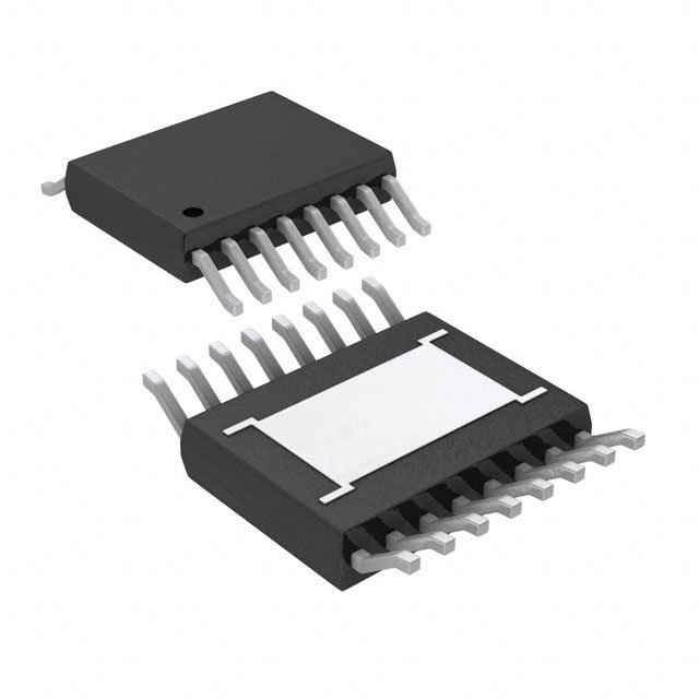
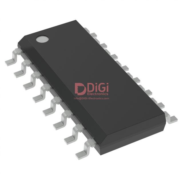
Package Options and Mechanical Data for VIPER28LDTR
The VIPER28LDTR system integrates two distinct package variants—SO16 narrow and DIP-7—catering to differing design constraints and assembly methodologies. The SO16 package excels in applications demanding high-density layouts, primarily due to its reduced footprint and the ability to maximize copper areas on multilayer PCBs. This optimization directly contributes to superior thermal management, mitigating heat stress in compact power stages. Engineers typically leverage the wider paddings of SO16 for efficient heat sinking, a crucial factor when designing power modules subject to elevated ambient temperatures or significant power throughput.
From a compliance perspective, both packages conform to ECOPACK® specifications, ensuring alignment with environmental protocols such as RoHS. This facilitates seamless adoption in markets where regulatory frameworks prioritize lead-free, sustainable electronics. Such compliance eases procurement and certification processes within global supply chains, minimizing design iterations and enabling a consistent lifecycle strategy for end products.
The mechanical data published by the manufacturer is precise, delineating pin pitch, body dimensions, and lead types. These specifications directly inform PCB layout approaches; for instance, the SO16’s tight spacing warrants attention to pad geometry and solder mask clearance to avoid bridging and ensure robust mechanical integrity post-reflow. In contrast, the DIP-7 variant remains advantageous for through-hole assembly in legacy systems or high-voltage isolation scenarios. Practical implementation shows that designers often exploit the DIP-7’s mechanical stability for quick prototyping or in conditions where mechanical shock is a concern.
Embedded within the integration workflow is the necessity for effective thermal simulation and modeling using the manufacturer’s detailed mechanical outlines. Such data underpins stack-up decisions in the early design phase, impacts thermal vias placement, and impacts reliability projections over extended operating cycles. The provided documentation streamlines inter-team collaboration between hardware and layout engineers, reducing ambiguity in the translation from specification to schematic to final physical instantiation.
Notably, selecting between SO16 and DIP-7 extends beyond assembly preference. The SO16 package, by virtue of its smaller form factor and thermal advantages, opens opportunities for miniaturized, high-efficiency power supplies where PCB space and cooling are at a premium. Conversely, the DIP-7 maintains relevance in retrofit applications and test environments, offering flexibility during rapid hardware iterations or fault analysis. Leveraging manufacturer-provided PCB recommendations, design teams can expedite certification and field validation, reflecting a direct pathway from component selection to commercially viable product deployment.
Potential Equivalent/Replacement Models for VIPER28LDTR
Potential Equivalent/Replacement Models for VIPER28LDTR span within the VIPerPlus family, which leverages monolithic high-voltage converter architectures. At their core, these devices integrate a high-voltage startup circuitry, PWM controller, and power MOSFET in a single package, optimizing for compact size and system reliability. The underlying topology enables robust energy efficiency, especially in low-standby applications. Close electrical relatives such as VIPER26 and VIPER17 maintain a shared foundation in primary-side regulation and comprehensive system protection, but each device targets nuanced application spaces through differences in power handling capabilities, switching frequency, and package footprints.
Selecting an equivalent or replacement model requires understanding both the application’s thermal and electrical boundaries. For moderate power levels and board-space constraints, VIPER17 offers a compact, efficient alternative, supporting power levels up to approximately 8 W in universal input applications. Conversely, VIPER26 can be advantageous in designs demanding higher output power or enhanced control features, owing to its increased current handling and improved switching dynamics. Critical evaluation parameters include maximum drain-source voltage, on-resistance, oscillator frequency, and protection schemes such as overload, thermal, and short-circuit safeguards. Variations in these factors can dictate noise immunity, EMI profile, and thermal dissipation strategies at the system level.
Application scenarios range from auxiliary power supplies in industrial automation systems to small-form-factor chargers and home appliance controllers. Across such environments, nuanced integration choices—such as selecting a device with advanced brown-out protection or zero-power mode—directly impact system longevity and certification margins. Integration with Flyback topologies, wide input ranges, and tight output regulation reinforce versatility, while practical deployment frequently involves iterative hardware revisions to optimize snubber circuits and EMI filtering in conjunction with device parameters.
Navigating the manufacturer’s selection guide serves as an efficient entry point but demands further diligence. Compatibility assessments extend beyond pin-count and nominal ratings to include subtle variances in soft-start behavior, burst mode operation, and fault management protocols. This diligence preempts costly design iterations and streamlines compliance with international safety standards, particularly in tightly regulated end-use categories.
A layered decision matrix, grounded in functional requirements and real-world board constraints, best supports optimal model selection. This approach narrows device choice to the subset balancing electrical fit, supply continuity, and forward-looking system scalability. Integration of up-to-date evaluation kits and reference designs accelerates development while minimizing unforeseen subtle incompatibilities, reinforcing the importance of an engineering-led, metrics-driven selection paradigm.
Conclusion
The VIPER28LDTR from STMicroelectronics exemplifies a compact, highly integrated flyback switcher IC tailored for AC-DC power conversion. At the device’s core, a high-voltage startup circuit operates seamlessly with an embedded PWM controller to enable efficient, low-component-count designs. Key underlying mechanisms include quasi-resonant switching and an advanced control loop, both contributing to minimized switching losses and reduced EMI signatures. These characteristics are crucial for achieving stringent energy efficiency and electromagnetic compatibility standards, particularly under international regulatory frameworks such as Energy Star and IEC 61000.
Robustness is built into the VIPER28LDTR through a comprehensive suite of protection functions—overload, overvoltage, overtemperature, and short-circuit protections are all on-chip. These features mitigate field failures and simplify system-level compliance, thereby streamlining qualification cycles in demanding industrial and consumer environments. The device’s accuracy in error detection and rapid response time are critical for ensuring uninterrupted operation, especially when deployed in environments with fluctuating line conditions or where thermal management is a constraint.
Configurability distinguishes the VIPER28LDTR in practical engineering scenarios. Adjustable parameters such as switching frequency and output voltage facilitate fine-tuning for diverse applications with varying load profiles, from standby power supplies to appliance controllers. When designing compact systems like smart meters or isolated auxiliary supplies, the small-form-factor package options—such as the standard SO16N—support high-density PCB layouts while maintaining desired creepage and clearance distances for safety certifications.
The device’s interoperability with the VIPerPlus series ensures a smooth upgrade path and design reusability. This compatibility simplifies migration strategies during cost reduction cycles or performance enhancements, increasing project agility without necessitating full board redesigns. In field deployments, assembling a suite of VIPerPlus ICs enables fast troubleshooting and streamlined inventory management, further reducing total cost of ownership.
When tuned to operate within manufacturer-recommended parameters, the VIPER28LDTR demonstrates stable startup and minimal audible noise compared to legacy topologies, especially in light-load or burst-mode conditions. Such characteristics enable compliance with modern DoE Level VI and ErP Lot 6 mandates, offering a competitive edge in markets where power budgets and acoustic profiles are closely scrutinized.
Selecting the VIPER28LDTR can serve as a strategic anchor for future-proof power architectures. Its blend of efficiency, flexibility, and integrated safety aligns well with both rapid prototyping cycles and long-term volume production, ensuring that designs remain resilient to evolving industry standards and operational demands.