 >
>


Product overview: VIPER17HD STMicroelectronics
The VIPER17HD, engineered by STMicroelectronics, embodies a high-voltage monolithic switching regulator tailored for offline flyback power conversion. Central to its architecture is an 800V avalanche-rugged power stage coupled with an advanced PWM controller. This pairing enables robust electrical overstress tolerance, enhancing system resilience against line transients and facilitating compliance with stringent reliability standards in demanding environments such as automation, industrial controls, and distributed consumer electronics.
The regulator operates at a fixed 115kHz switching frequency, striking a balance between transformer size, EMI management, and efficiency. This frequency selection is deliberate, designed to minimize core losses and maximize energy transfer, optimizing thermal performance in compact form factors. Designers benefit from the integrated start-up circuitry, which eliminates the need for discrete high-voltage bias circuits, accelerating development cycles and reducing both board space and BOM cost. The on-chip control logic merges soft-start and frequency jitter functionality, ensuring smooth output voltage ramp-up and improved EMI signature—a feature particularly relevant in noise-sensitive designs.
Hardware integration extends further with comprehensive automated protections: cycle-by-cycle current limiting, thermal shutdown, and built-in overload mechanisms. Such provisions are vital for long-life operation in SMPS applications exposed to unpredictable supply conditions or fluctuating load profiles. Experience in diverse deployment scenarios has highlighted the effectiveness of the VIPER17HD’s protections in preserving downstream components and safeguarding overall power system integrity, even as operational parameters shift over time.
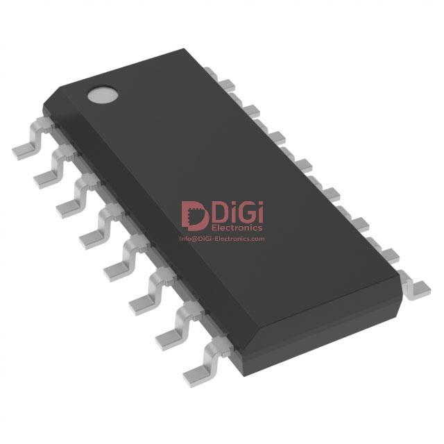
The 16-SO package underscores the device’s alignment with current manufacturing standards, supporting reflow soldering, automated placement, and optimal thermal dissipation. This form factor, combined with the regulator’s low external component count, translates directly into streamlined PCB layouts and repeatable, compact designs across mass production contexts.
From a system-level perspective, the VIPER17HD is ideally positioned for applications such as auxiliary power supplies in appliances, smart meters, or LED drivers, where efficiency, reliability, and cost pressure coalesce. Its topology-agnostic nature and robust voltage handling enable direct operation from universal AC mains, simplifying design for global markets. The chip’s internal feature set implicitly promotes energy conservation—minimizing standby consumption while ensuring high conversion efficiency at full load.
An additional layer of insight reveals that integrating multiple support functions within the VIPER17HD encourages a shift in power supply design philosophy, moving away from discrete complexity toward monolithic simplicity. This trend supports rapid prototyping and iterative improvement, enabling performance tuning during development without hardware rework.
In essence, the VIPER17HD is engineered to bridge the gap between robust protection and minimalistic circuit design, delivering a refined platform for efficient, resilient SMPS architectures. Its optimized combination of advanced control, integrated protection, and package versatility makes it an asset in modern power conversion solutions where reliability and design agility are paramount.
Key features and technology highlights of VIPER17HD STMicroelectronics
VIPER17HD from STMicroelectronics epitomizes a modern, integrated solution for compact power conversion, leveraging a high-voltage 800V avalanche-rugged N-channel MOSFET as its central switching element. The device accommodates severe line conditions and surge environments by absorbing voltage transients without device degradation. This robustness results from advanced oxide and cell engineering, yielding essential margin in real-world lighting, home appliance, and industrial interfaces, where grid disturbances and overvoltages persist.
Mitigation of electromagnetic interference is directly addressed by the implementation of frequency jittering within the pulse-width modulation oscillator. The oscillator’s nominal switching frequency of 115kHz is dynamically modulated over a defined spread, distributing harmonic energy and reducing peak spectral emissions. This feature targets lower cost EMI filter design while securing compliance with stringent EMC standards. The architecture minimizes board-level redesigns and field failures relating to radiated and conducted emissions—a critical requirement in densely packed and multi-converter assemblies.
Protection is organized as a comprehensive, multi-tiered suite adaptable to end-application constraints. Adjustable current limiting, precise overvoltage detection, and soft-start mechanisms collaboratively optimize converter startup and normal operation, averting destructive stress on passive and active components. Auto-restart and hysteresis-driven thermal shutdown prevent repeated fault cycling and excessive junction temperature excursions during abnormal loads or cooling failures. The brown-out detection reliably identifies insufficient input voltages, maintaining converter control integrity and averting system latch-ups or erratic resets—features appreciated when operating at the margins of AC supply tolerance.
Efficiency in off-mode and light-load scenarios is prioritized by the adoption of burst-mode control, delivering sub-30mW standby consumption at high-line (265VAC). This approach exploits inherent dead-time extension and low switching frequency thresholds to minimize core losses and switching events, ensuring not just compliance with international energy standards but also improved thermal management and lifetime expectancy for both magnetic and semiconductor elements.
Start-up reliability, a critical metric in universal power designs, is achieved through the integrated high-voltage start-up generator connected directly to the DRAIN pin. This obviates the need for external biasing circuitry, reduces component count, and ensures rapid, deterministic converter engagement immediately upon line application or recovery from brown-out. Key advantages surface in white goods, smart meters, and auxiliary SMPS channels where board space is constrained and regulatory standards are imposing ever-stricter inrush and start-up criteria.
Experience indicates that the combination of a rugged main switch, sophisticated control features, and system-level protections distinctly simplifies PCB layout and reduces development iterations. VIPER17HD’s integration helps address EMI and energy compliance synchronously, streamlining certification timelines and facilitating faster market entry for power supply platforms aimed at consumer, utility, and industrial sectors. This convergence of high-voltage robustness, EMI-aware design, configurable safety, and power efficiency substantiates the device as a strategic choice for next-generation auxiliary and small power systems seeking both resilience and regulatory congruence.
Electrical specifications and operating characteristics of VIPER17HD STMicroelectronics
Electrical specifications of the VIPER17HD from STMicroelectronics define the operational backbone for robust power supply design, making a careful assessment of each parameter vital for optimal system integration. At the silicon level, the device exhibits an absolute maximum drain-source voltage (BV_DSS) of 800V, positioning it to handle demanding off-line switch-mode power topologies, especially those susceptible to severe line transients. The typical static on-resistance (R_DS(on)) of 20Ω at 25°C, while not ultra-low, is balanced by the device’s integration of a high-voltage start-up cell and an efficient power management core, enabling operation in compact, high-voltage environments with constrained thermal budgets.
Thermal considerations are critical in translating these package ratings to system reliability. The SOT-23-6L or similar low-profile package necessitates accurate layout practices. Manufacturer-provided thermal resistance (junction-to-ambient and junction-to-case) values serve as a baseline, but actual performance hinges on copper area allocation beneath the DRAIN pin. Experience shows that maximizing PCB copper for heat spread, and optimizing via deployment beneath the thermal pad, yields measurable improvements in temperature margin during prolonged load conditions. In enclosed designs, forced airflow or strategic placement near chassis edges further reduces local hot spots, whereas open-frame systems benefit from increased convection, allowing for higher continuous output power without reaching derating thresholds.
From an electrical performance standpoint, integrated supply management delivers a tightly regulated start-up sequence. The V_DD start-up threshold ensures the controller only begins switching once auxiliary bias is established, effectively eliminating oscillatory undervoltage lock-outs during brown-in events. Drain current limiting is governed by both cycle-by-cycle regulation and fast protection comparators, a methodology that enhances short-circuit robustness and power limiting under fault loads. The fixed oscillator frequency, typically in the 60–132 kHz range depending on the chosen variant, assists in EMI planning and transformer design, while the precise feedback voltage reference (often at 0.6V ±2%) permits tight output regulation, which is particularly relevant in applications driven by ever-increasing stand-by and efficiency targets.
System-level design choices hinge on these characteristics. The device’s ability to combine integrated high-voltage start-up, current-mode PWM control, and robust fault protection within a minimal footprint considerably simplifies board architecture. In practical scenarios, the simplified auxiliary winding design enabled by a wide V_DD operating range frequently translates into reduced BOM cost and improved manufacturability. This level of integration mitigates the need for external start-up resistors, reducing both standby losses and assembly variance, a subtle yet measurable gain in low-power scenarios.
A crucial insight emerges regarding the interplay between thermal engineering and electrical stress. While official datasheets specify conservative limits, real-world performance is defined by the effectiveness of board-level heat extraction and the rigor of system protection loop design. For engineering teams, direct correlation of device temperature profiles with external transient events and parametric drift often reveals underutilized design margins, which can be reclaimed through layout refinement, offering a path to either power density gains or increased reliability, depending on application priorities.
In summary, the VIPER17HD’s specifications should be interpreted as the framework for comprehensive system optimization. Systems requiring universal AC input, stringent efficiency, and high reliability stand to gain the most from thorough exploitation of these characteristics, provided that attention to both thermal path engineering and closed-loop control stability is sustained from the schematic stage through PCB and system validation.
Functional operation and protection mechanisms in VIPER17HD STMicroelectronics
VIPER17HD from STMicroelectronics incorporates a constellation of functional strategies and protective schemes engineered for stability, efficiency, and robust safety across diverse power conversion scenarios. At its core, current mode control leverages a sense-FET topology to enable precise drain current detection without adding series losses. This fundamental approach grants real-time dynamic adjustment through cycle-by-cycle modulation, empowering more accurate current limiting and facilitating rapid response to load or fault transients. Fine-tuning the peak current threshold via the CONT pin—achievable by selecting an appropriate RLIM value—further tailors performance for custom system requirements, balancing protection headroom with operational overhead.
Protection logic within VIPER17HD operates on several hierarchical layers; voltage and current overloads are swiftly recognized via integrated feedback and monitoring circuitry. The internal controller orchestrates either auto-restart or hiccup modes based on event severity, significantly reducing thermal and electrical stress. This self-contained fault management architecture isolates malfunctioning conditions, preserving converter integrity and ensuring automatic, repeatable recovery—a necessity for applications exposed to unpredictable grid events.
During initial energization or post-fault recovery, the soft-start mechanism plays a critical role in suppressing inrush currents and mitigating secondary-side stress. By orchestrating gradual ramp-up of output voltage and current, the controller averts saturation events in magnetics and excessive diode stress, enhancing system durability. Reliable startups and seamless fault transitions are critical in both consumer and industrial ecosystems, where repeated cycling is common and component longevity is a primary concern.
VIPER17HD further embeds brown-out protection, fundamental for stable behavior on fluctuating AC mains. The comparator subsystem continuously monitors input voltage, instantaneously gating the output if sag conditions breach preset thresholds. This intervention protects downstream circuits, averting supply instability that might otherwise propagate systemic faults in sensitive microcontroller or motor-drive stages.
Under light or no-load operation, dynamic transition to burst mode reduces average switching frequency—the chip intelligently modulates its power delivery cadence, slashing quiescent losses and advancing regulatory compliance for energy efficiency. This layered power management is especially valuable in standby and low-duty cycle applications, where minimizing no-load draw directly impacts product ratings and operational costs.
Thermal protection is realized through hysteresis-based shutdown, systematically disengaging the output upon sustained overheating and re-enabling it only under safe temperature conditions. Such closed-loop thermal management fortifies long-term reliability under high ambient or constrained cooling environments, protecting both individual devices and the system enclosure from thermal runaway scenarios.
Operational experience demonstrates that tightly integrated, multi-layered functional and protection architectures—such as those in VIPER17HD—enable designs with superior resilience and reduced bill of materials. The inclusion of independently adjustable current limitation and robust fault handling mechanisms supports seamless adaptation across a range of transformer sizes and output profiles, streamlining system qualification and accelerating time-to-market. Intrinsically, the optimal interplay between sensing granularity, programmable thresholds, and coordinated protection responses sets a new reference point for intelligent offline converter implementation in evolving power electronics portfolios.
Application scenarios and implementation considerations with VIPER17HD STMicroelectronics
The VIPER17HD from STMicroelectronics integrates high-voltage startup, PWM control, and protection features in a single, compact package, making it adaptable across a wide range of flyback converter scenarios. Its primary target applications span compact adapters for consumer electronics—such as mobile device chargers, gaming peripherals, and personal care gadgets—where efficiency, size, and regulatory compliance drive design decisions. In these environments, the VIPER17HD's quasi-resonant operation delivers both high conversion efficiency and low electromagnetic interference, supporting designers in meeting increasingly stringent energy standards.
In auxiliary power supplies for LCD/PDP TVs, monitors, audio equipment, and computer peripherals, the need for stable, isolated low-power rails can be addressed efficiently with the VIPER17HD’s integrated high-voltage MOSFET and standby management. Industrial and professional lighting systems, especially those requiring high-reliability isolated supplies for controls or efficient LED drivers, benefit from its robust protection and configurable startup behavior. The device also accommodates demanding SMPS in set-top boxes, white goods, and small appliances, where thermal and electrical stress must be managed within tight form factors.
A layered approach to implementation begins with PCB design for thermal management and electrical integrity. The DRAIN pin, acting both as an HV input and as a thermal conduction path, necessitates precise copper area allocation and via positioning underneath or adjacent to the pin to ensure efficient heat spreading and to reduce switching noise. In high-density boards, partitioning sensitive feedback lines away from switching nodes further minimizes parasitic coupling—a lesson often validated during emissions troubleshooting.
Hardware configurability through key pins, specifically CONT and BR, underpins the device’s adaptability. The CONT pin allows adjustment of current protection thresholds and output overvoltage limits by selecting external resistors and capacitors to match the application's unique transient demands. Practical experience suggests that conservative selection of these elements prevents nuisance tripping while ensuring fault protection. The BR pin, when set precisely, enforces brown-out protection tailored to the local AC mains profile, safeguarding both the converter and downstream loads against undervoltage startup and erratic line conditions; this has proven invaluable in geographically diverse installations.
Achieving loop stability and precise output regulation resides in the careful design of the feedback network. The FB pin, interfacing with optocoupler and reference circuits, dictates dynamic response through choice of compensation components. Selecting RC values that balance gain and phase margin mitigates risk of subharmonic oscillations and maintains consistent behavior during load transients or soft-start sequencing. Experience demonstrates that bench validation with actual load profiles reveals small-signal instabilities not always predicted by simulation alone, reinforcing the need for both analytical and empirical loop tuning.
While the VIPER17HD’s integrated protection mechanisms reduce design complexity, extracting maximum advantage requires a holistic view: optimal thermal layout, deliberate pin configuration, and comprehensive feedback tuning. Strategic trade-offs—such as prioritizing brown-out immunity over minimal standby power—can be guided by the deployment environment and compliance targets. Core insights emerge from field deployments, where marginal layout changes yield tangible improvements in EMI and thermal headroom, illustrating that fastidious attention to implementation details is instrumental in leveraging the full capabilities of the VIPER17HD.
Packaging, environmental compliance, and physical details of VIPER17HD STMicroelectronics
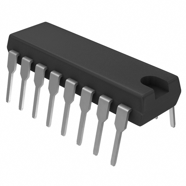
Packaging for the VIPER17HD from STMicroelectronics is engineered to address diverse application constraints, emphasizing both high-voltage robustness and global regulatory compliance. The component is available in SO16 narrow and DIP-7 formats; each provides tailored physical architectures designed to optimize creepage and clearance distances, reflecting direct adherence to nuanced IEC requirements for safe electrical isolation. The SO16 narrow package is specifically optimized for compact board designs where stringent spacing must be balanced with high-density layouts, mitigating the risk of dielectric breakdown under elevated voltages. DIP-7, by contrast, offers a form factor well-suited to through-hole assembly, favoring applications where PCB robustness or ease of inspection is essential.
Integrated within the packaging ecosystem is STMicroelectronics’ adherence to ECOPACK specifications—an industry-standard framework underpinning the reduction of hazardous materials and environmental impact. This extends from the exclusion of lead and halogens to the use of recyclable materials in both the carrier and encapsulant, facilitating conformity with RoHS and REACH regulations. When scaling from prototyping to volume production, these environmental standards streamline supply chain integration, minimizing compliance overhead for ODMs and OEMs targeting international markets.
Pin geometry and mold profiles demand careful handling during board assembly. Mechanical tolerances—such as permissible levels of flash, gate vestige, and standoff—require precise soldering process adjustment, particularly in automated manufacturing settings. Disregard for these micro-dimensional parameters can propagate cold joints, delamination, or stress fracturing—issues that have downstream effects on device thermal reliability and long-term operational integrity. Notably, attention to the mating of PCB land patterns and projected thermal path optimization strongly influences dissipation in high-frequency switching contexts, enabling tighter thermal budgets in densely integrated designs.
A layered approach to PCB design, integrating both mechanical and regulatory concerns from the outset, consistently yields reduced rework rates and enhanced long-term field performance. For applications in power conversion, appliance control, or industrial inverters, success hinges on rigorous conformance to package-specific footprint recommendations, as well as vigilant management of reflow profiles. Iterative feedback from DFM (Design for Manufacturability) processes often highlights the subtle influence of package-induced parasitics and standoff variation, which can be critical in high-speed, high-voltage domains.
In summary, the intersection of environmental compliance, physical package engineering, and assembly process discipline for VIPER17HD converges to enable advanced, robust power design. The informed selection and application of these packages, with deep consideration of their physical and regulatory attributes, can be a decisive factor in achieving scalable, globally deployable solutions.
Potential equivalent/replacement models for VIPER17HD STMicroelectronics
When examining suitable alternatives to the VIPER17HD from STMicroelectronics, the analysis must start at the fundamental architecture and key operational parameters. The VIPER17HD, part of the VIPerPlus family, integrates an 800 V avalanche-rugged MOSFET and PWM controller for off-line power conversion, targeting compact and highly efficient switched-mode power supplies (SMPS) under stringent EMI and power density targets. Any cross-reference selection begins with a close evaluation of switching frequency, voltage handling, and feature integration, as these factors define not only regulatory compliance and thermal performance but also the breadth of application compatibility.
Within the same family, the VIPER16 emerges as a viable substitution primarily for designs where the frequency envelope is lower. By operating at a reduced switching rate, the VIPER16 inherently produces lower EMI and can, in some cases, alleviate the filtering requirements on the input side. This characteristic directly benefits retrofit or cost-constrained layouts, particularly in markets less sensitive to high-frequency noise or where board-level EMC countermeasures are impractical. However, the transition from the VIPER17HD to VIPER16 mandates a thorough recalculation of transformer design and output filtering to maintain efficiency and regulation stability.
For contexts where the VIPER17LN is considered, differences in switching frequency and pinout must be carefully matched to platform needs. This variant may offer alternate frequency plans or protection logic, serving projects where legacy footprints dictate physical compatibility or where selective adjustment of timing parameters mitigates inrush or overshoot events. Experience demonstrates that in multi-variant designs, using the VIPER17LN simplifies design reuse across product families by tailoring features without significant PCB revision, particularly where BOM standardization can reduce sourcing risk.
Higher wattage or more integrated features are common drivers for transitioning to the VIPER22A or VIPER28. These parts expand power handling capability and typically include advanced integrated safety features such as enhanced thermal foldback, overvoltage, and brownout protections. In practical terms, the move to these models is observed when design scaling or regulatory shifts—such as tougher SELV isolation or standby power restrictions—necessitate higher integration with minimal board area impact. The elevation in switching frequency and current capability must, however, be balanced against increased thermal management complexity, sometimes requiring shifts to larger or thermally optimized packages.
A robust cross-selection demands a systematic alignment of absolute maximum ratings, switching characteristics, and available protection mechanisms. Package type also plays a central role, as re-qualification for a different mechanical footprint can negate the initial supply chain or cost advantages. Practical sourcing constraints further highlight the necessity to simulate candidate replacements under worst-case electrical and thermal conditions, confirming not only drop-in capability but the endurance under abnormal line and load excursions.
An implicit insight arises from these common engineering scenarios: the flexibility built into the VIPer series enables not just direct replacement, but also strategic design iterations—allowing product lines to adapt for both cost-driven and performance-driven market segments. This modularity in the design toolkit future-proofs supply strategies in a landscape of fluctuating part availability while maintaining a consistent core platform. Through pre-emptive benchmarking and empirical validation, it is possible to maintain regulatory continuity and performance targets without sacrificing design agility.
Conclusion
The VIPER17HD from STMicroelectronics represents an advanced integration of flyback switching regulator technology designed to address the demanding requirements of modern power electronics. At the core, the device incorporates a high-voltage avalanche-rugged power MOSFET with a highly efficient controller, enabling direct operation from rectified mains voltages up to 265 VAC. Its switch-mode architecture leverages quasi-resonant and pulse-by-pulse current mode control, minimizing both conduction and switching losses, which directly contributes to achieving high conversion efficiency across a broad load range.
Protection mechanisms form a critical aspect of the VIPER17HD’s design. The chip includes built-in protections such as output overvoltage, overtemperature, short-circuit, and soft-start functionalities. These features operate autonomously and trigger rapid shutdown or current limitation routines, shielding downstream circuitry without requiring external intervention. Such embedded intelligence streamlines compliance with international safety and energy regulations, accelerating development cycles for power supplies targeting certifications like IEC 62368.
Configurability is a defining strength. By carefully selecting external components, engineers tailor the oscillator frequency, compensation network, and output voltage scaling. This flexibility enables optimization for various applications, from ultra-low standby power operation—where burst mode dramatically reduces no-load consumption—to robust full-load performance in industrial control or white goods. For instance, tuning the compensation network not only ensures loop stability under dynamic loading but also mitigates electromagnetic interference (EMI) concerns, essential in regulatory-constrained environments. A well-placed snubber and compact layout around the MOSFET help suppress voltage spikes, reinforcing reliability in the presence of input surges.
Practical implementation demands particular focus on PCB layout. Minimizing trace inductance and capacitor ESR in the high-current switching path consistently yields improvements in conducted and radiated EMI. Separation of high-voltage and low-voltage domains on the PCB further enhances safety and reduces cross-talk, a lesson repeatedly validated in both high-density commercial adapters and industrial sensor nodes.
The device’s compactness and integrated protection have enabled a new class of cost-efficient, single-sided PCB power supply designs, particularly valuable in space- and weight-constrained systems. Its robust handling of fast line transients and brownout conditions unlocks deployment in geographies with unstable mains. These attributes, coupled with the predictable start-up and shutdown behavior mediated by the soft-start and brownout detection functions, not only increase product robustness but also assure designers of consistent field performance without elaborate external circuitry.
Integrating these advanced mechanisms within a monolithic device simplifies the supply bill of materials and aligns with industry trends toward higher efficiency and system miniaturization. The VIPER17HD thus stands out as an enabling component for highly reliable, standards-compliant designs— bridging the gap between stringent compliance requirements and aggressive cost, size, and efficiency targets now prevalent in consumer and industrial power applications.