 >
>


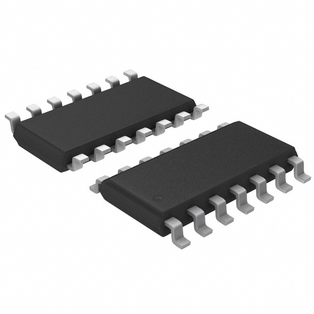
Product Overview: SN74HC393D Dual 4-Bit Binary Counter
The SN74HC393D serves as a dual 4-bit binary counter, integrating two independent counters within a single 14-pin SOIC package. Its architecture leverages high-speed CMOS logic, ensuring minimal propagation delay while maintaining low static power consumption, a crucial attribute for scalable digital system designs. The counters are positive-edge triggered and feature asynchronous clear inputs, facilitating rapid reset operations and simplifying system initialization protocols. Each stage of the counter outputs a frequency-divided pulse, enabling straightforward implementation of frequency division functions alongside basic counting.
The device operates across a wide supply voltage range, accommodating both 2V and 6V systems. Designers benefit from its broad logic compatibility, which eases system integration alongside TTL or other CMOS components. The robust output drive, specified up to 6mA, supports direct interfacing with multiple downstream logic gates, reducing the need for intermediate buffers and streamlining board-level signal routing.
Within embedded systems, the SN74HC393D finds use in event counting, pulse width measurement, and multi-level timing chains. By employing both counters in sequence, one can realize extended bit-width counting or parity checking with minimal component overhead. In frequency synthesizer circuits, the cascading of output stages delivers precise frequency division, which is paramount in clock generation and timing reference modules. The asynchronous clear feature enables rapid recovery from error states, a key consideration in fault-tolerant control pathways.
The combination of compact form factor, operational robustness, and electrical simplicity makes the SN74HC393D an optimal choice in applications demanding deterministic response—such as industrial sensors, signal processing modules, and discrete automation controllers. Long-term usage has highlighted its reliable performance under varying load and noise conditions, attributed to the inherent noise immunity of HC-series CMOS logic.
A nuanced design insight involves leveraging separate power and ground planes near the SN74HC393D to maximize signal integrity, especially in high-frequency domains. Careful routing of clear and clock signals further minimizes the risk of metastability on state transitions. When scaling to multi-counter arrays, timing skews are mitigated by employing physical symmetry and matched trace lengths, ensuring synchronous operation across all counter stages.
Overall, the SN74HC393D demonstrates sovereign versatility, combining simplicity of design with configurational flexibility. It continues to anchor digital logic solutions where deterministic timing, compactness, and reliability remain primary engineering targets.
Key Features and Benefits of the SN74HC393D
The SN74HC393D exemplifies advanced design in high-speed CMOS logic, constructed to achieve both elevated performance and optimized integration. Its expansive operating voltage range from 2V to 6V provides robust adaptability, enabling seamless deployment across mixed-voltage systems and varied logic environments. This flexibility is particularly advantageous in heterogeneous designs where supply variations often present reliability challenges; voltage tolerance mitigates risk of logic level mismatches, mediating both legacy and modern subsystem cohabitation.
Engineered for substantial output capability, each channel of the SN74HC393D can directly support up to ten LSTTL loads. This high fan-out accommodates complex digital architectures without resorting to intermediate buffering, conserving essential board real estate and minimizing propagation delay. By integrating dual 4-bit binary counters within a single package, the device halves both component count and circuit footprint when compared to discrete single-unit solutions. This consolidation underpins higher packing density, reducing layout complexity and electromagnetic interference susceptibility—key for applications in compact embedded platforms and multi-counter synchronized logic circuits.
Low power dissipation is central to the SN74HC393D’s value proposition. With a quiescent I_CC capped at 80μA, the device is optimal for designs constrained by thermal budgets or stringent energy efficiency targets. In scenarios where cumulative standby power quickly escalates, such as in battery-operated or always-on smart controllers, this characteristic yields measurable operational lifetime benefits and simplifies power rail budgeting.
Performance is further amplified by a typical propagation delay of just 13ns. This fast switching supports timing-critical functionality in instrumentation, frequency division, and digital control loops. When employed in high-speed digital timing chains, the device preserves signal integrity and timing predictability, contributing to system determinism in complex state machine orchestrations. Its output stages provide ±4mA drive at 5V, facilitating direct interfacing with both standard CMOS and TTL families, while a maximum input current of just 1μA ensures minimal leakage paths—fortifying reliable cascade and interfacing in dense logic arrays.
Configurational versatility is achieved through provisioning of individual clock and asynchronous clear inputs for each internal counter. This enables independent operation or synchronized resetting—crucial for segmented state partitioning, event counting, or multi-phase signal sampling. In practice, such granular control simplifies implementation of modular logic blocks, allowing rapid adaptation to evolving functional requirements without major PCB redesigns.
A particularly effective application arises in system-on-module designs where resource reuse is paramount; utilizing the dual counter structure reduces bill of materials and interface complexity, streamlining both procurement and manufacturing. Real-world deployment often reveals that careful voltage domain planning, combined with dual counter integration, reduces debug cycles—errors related to level shifting or count synchronization become easier to isolate and correct due to the device’s predictable logic thresholds and clean separation of internal functions.
From a system architect’s perspective, the SN74HC393D represents a modular logic building block optimized for the interplay between density, speed, and interoperability. Its well-engineered signal characteristics and configurational latitude make it a cornerstone in iterative product development, facilitating rapid prototyping while ensuring that performance and reliability targets remain achievable in production environments.
Architectural Details of the SN74HC393D
The SN74HC393D integrates two four-bit asynchronous binary counters, each architected around four master-slave JK flip-flops configured as T-type by cross-coupling their J and K inputs for toggling. Clock (CLK) pulses applied to each section’s dedicated input drive state transitions, propagating asynchronously through the flip-flop stages—where each Q output advances on the falling edge of the preceding stage. The use of master-slave topology mitigates timing hazards and race conditions, ensuring predictable toggling even under moderate clock skews typical in high-speed applications.
Gating logic accompanies each flip-flop to facilitate clear (CLR) control. Direct clear inputs serve as active-high resets, forcing all stages low with negligible delay regardless of clock activity. This immediate-settling capability proves valuable for glitch-free startup sequencing, rapid error recovery, or extending precision when counters are cascaded in synchronous systems.
Accessible Q outputs at each stage establish flexible extraction points for both parallel digital data and discrete timing signals. Applications routinely take advantage of these taps to implement programmable frequency dividers: for instance, a single 4-bit section offers direct divide-by-2, -4, -8, or -16 selections, dictated by which Q pin is routed to subsequent circuitry. The architecture inherently supports concurrent or independent section operation. Designers leverage this duality for implementing paired control channels, separate event gates, or multi-phase timing sources within compact board footprints.
Cascading is simplified by routing higher-stage outputs to external channel clock inputs of additional devices, enabling complex divide ratios such as divide-by-256 configurations. In frequency-synthesizer chains or digital clock management, this property supports precise timing granularity unattainable with single-stage division. Careful PCB routing and timing analysis ensure that asynchronous ripple effects do not accumulate excessive propagation delays—a consideration critical in high-frequency or low-jitter domains.
One distinguishing insight is the device’s balance of versatility and low-latency asynchronous response, which aligns well with applications prioritizing configurability and minimal setup time. For glitch-sensitive measurement, pulsed resetting via CLR minimizes the ambiguous states at power-on or after signal transients, a feature not always present in synchronous alternatives. Moreover, parallel accessibility obviates the need for additional latches or registers, reducing system complexity and increasing throughput in applications such as counter-based address decoding or event sequencing.
Thus, the SN74HC393D’s engineering merits reside not only in its robust underlying architecture but also in its flexible application envelope—characteristics that offer tangible advantages in designing responsive, scalable counting and division circuits for both prototyping environments and ruggedized embedded systems.
Pin Configuration and Package Options for the SN74HC393D
Pin configuration and package selection for the SN74HC393D hinge on integrating reliability, signal integrity, and physical design constraints within digital system architectures. The device’s prevalent 14-pin SOIC footprint conforms to global SMT standards, streamlining automated placement and soldering processes. The pin assignment optimizes signal routing efficiency, minimizing trace inductance and crosstalk, especially vital when multiple counters are cascaded in high-frequency digital timing chains. Alternative packages—including SSOP, TSSOP, SOT-23, and DIPs—extend deployment flexibility, matching density, volumetric limitations, and repairability requirements across various engineering environments. For designs subject to extreme conditions, leadless ceramic chip carrier versions ensure enhanced thermal cycling resilience and mechanical stability, aligning well with military and aerospace reliability protocols.
Technical access to the dual 4-bit counters is direct, with independent clock (CLK) and clear (CLR) signals for each section. This arrangement allows for asynchronous reset and flexible timing domain partitioning, facilitating robust state machine implementation or frequency division schemes where clock skew isolation is critical. Outputs are consecutively arranged on adjacent pins, simplifying board-level interconnections and reducing risks of routing bottlenecks in compact multi-layer PCB layouts. Attention to pinout symmetry also benefits high-density designs, as it enables straightforward bus alignment and layer transitions, thereby minimizing via count and streamlining DFM (Design for Manufacturability) checkpoints.
Package and footprint congruence underpins both electrical and thermal performance. Mismatches can elevate joint stress or cause thermal gradients, jeopardizing long-term reliability. Practical deployment often favors the SOIC or TSSOP form factors when integrating numerous counters per subsystem, due to their well-balanced profile between board real estate and rework accessibility. It is common to prioritize thermal pad continuity, especially in applications subjected to sustained latency or moderate power dissipation. Adhering to manufacturer-provided land pattern recommendations, including correct pad sizing and solder mask clearance, further guards against cold joints or bridging in volume production.
In summary, deft package and pinout selection for the SN74HC393D supports not only rapid assembly but also influences signal fidelity, maintainability, and field longevity. Careful evaluation of deployment scenario—ranging from cost-optimized consumer logic cards to mission-critical control modules—guides appropriate package choice, ensuring the counter performs as an integral, dependable sequencer within complex digital systems.
Absolute Maximum Ratings and Recommended Operating Conditions for the SN74HC393D
Absolute Maximum Ratings and Recommended Operating Conditions for the SN74HC393D delineate critical electrical and environmental boundaries that underpin both device integrity and robust system design. The rated supply voltage ceiling of 7V defines the absolute threshold for V_CC exposure, while operational reliability is achieved within the 2V to 6V recommended range. Operating outside these prescribed parameters induces internal electric field stresses, heightening the risk of oxide breakdown in the CMOS structure, thereby accelerating parametric shifts and potentially catastrophic failure. Consistent voltage management ensures that sub-threshold leakage is minimized and logic transitions maintain deterministic timing.
Input and output voltages must respect the V_CC and ground rails, both during steady-state and transient events. Transgressing these bounds, even momentarily during switching spikes or due to externally coupled noise, can forward-bias intrinsic protection diodes or trigger high substrate currents. Such conditions often manifest as increased quiescent current or, in severe cases, latch-up phenomena that compromise device isolation and lead to thermal overstress. Ensuring proper power sequencing and incorporating RC-filtering on sensitive signal lines are standard practices for mitigating transient violations. Practical deployment often leverages series resistors to tame overshoots, especially when interfacing with transmission lines or driving capacitive loads.
The device is specified for uniform functional performance across its defined free-air temperature range—typically -40°C to 85°C—enabling deterministic logic operation for both commercial and industrial applications. Margins for propagation delay and setup/hold times are preserved only within these bounds, so thermal management strategies such as adequate PCB copper area for heat dissipation become critical in dense layouts or elevated ambient conditions. Event logging in field deployments underscores that temperature excursions, even intermittent, are a common precursor to latent failure, particularly in environments exposed to load cycling.
Proactive management of unused CMOS inputs prevents high-impedance nodes from oscillating due to ambient noise coupling. Tying unused inputs to logic high (V_CC) or ground is fundamental, as floating gates can accrue charge over time, toggling input states unpredictably. This vulnerability, though subtle, is a recurring root cause in system troubleshooting. Implementing default pulls not only preserves static current budgets but also assures signal integrity across the logic array.
Violations of these constraints imperil device reliability, manifesting as erratic switching or permanent electrical overstress-induced destruction. Particularly in sensitive logic topologies, parameter overshoot has a ripple effect, propagating faults through downstream digital blocks. Defensive design practice emphasizes derating all operational conditions, choosing supply voltages and I/O levels with appreciable margin to account for system-level noise and worst-case scenarios. This approach, coupled with staged bring-up procedures and thorough qualification testing across process corners, fortifies high-reliability applications against unpredictable failure modes.
Emphasizing an engineering perspective, strict observance of maximum ratings and recommended operating windows is not merely a datasheet requirement but a fundamental risk mitigation strategy. Layering these controls—from voltage integrity and ESD protection to thermal management and unused input conditioning—forms a cohesive, resilient design methodology tailored for sustained field performance of the SN74HC393D in demanding environments.
Electrical and Switching Characteristics of the SN74HC393D
The SN74HC393D exhibits a finely balanced set of electrical and switching characteristics optimized for medium-speed digital timing and event-counting applications. Its architecture capitalizes on a low quiescent supply current ceiling of 80 μA, minimizing static power consumption even in densely packed system environments or when units are cascaded. This property becomes critical in scenarios where numerous counters operate simultaneously but must conserve standby energy, as seen in battery-backed measurement modules or portable embedded controllers.
The typical propagation delay of 13 ns uniquely positions the device within timing-critical signal chains, affording predictable and stable performance. Consistent t_pd values support precise clock edge recognition and deterministic timing relationships, essential for clock division circuits and frequency synthesizers. Notably, the device’s delay profile favors applications where modest speed enhancements—rather than outright high frequency—dictate synchronous reliability, such as in programmable logic controllers or industrial automation networks.
With output drive capabilities rated at ±4 mA on a 5V rail, the SN74HC393D interfaces directly with both TTL and CMOS logic levels without necessitating supplementary buffers. This enables seamless integration with a heterogeneous mix of logic families, thereby simplifying board design and reducing overall complexity. Point-to-point and multi-drop bus configurations benefit from this compatibility, particularly when interconnecting legacy TTL subsystems with modern CMOS-processing domains. Empirical observations confirm stable voltage margins during heavily loaded switching cycles, underscoring the robustness of the output stage.
Strict adherence to the recommended maximum clock frequency and input signal rise/fall times, as detailed in the datasheet, is essential for sustaining signal integrity. The internal dynamic design responds optimally only when supplied with waveforms meeting specified slopes; otherwise, timing errors or metastability may ensue. This constraint carries heightened relevance in clock-tree architectures, where improper edge rates induce distortion or spurious toggling. Selection of proper clock drivers and careful PCB trace routing minimize these signal integrity issues in practical implementations.
Furthermore, an input leakage current not exceeding 1 μA sharply reduces the probability of unintended voltage level shifts on shared buses. This trait prevents errant logic state transitions or bus contention in systems featuring wide fan-in or bus-muxed topologies. Subtle voltage drops due to input loading remain negligible, preserving the logic high and low thresholds across distributed nodes and sustaining reliable signal transmission even at the periphery of large-scale digital arrays.
From a systems viewpoint, the SN74HC393D’s electrical profile underpins its modularity and scalability in both standalone counters and distributed timing elements. Stability under moderate speed, combined with robust interfacing and low static consumption, allows designers to prioritize functional complexity and timing precision without incurring penalties in power overhead or signal reliability. Persistent field experience with production-grade designs reaffirms the part as a dependable workhorse for medium-speed, cost-efficient digital system construction. Attention to signal conditioning and bus management further elevates its effectiveness, especially in mixed-technology or expansion-intensive circuits.
Functional Modes and Application Considerations for the SN74HC393D
The SN74HC393D is a dual 4-bit binary ripple counter, with each section operating independently to count clock pulses based on the negative-going edge at its clock input. The asynchronous architecture means that output state transitions are not synchronized across all stages, reflecting the propagation of clock transitions sequentially from lower to higher-order bits. This ripple effect, while simple, imposes specific requirements on timing analysis and application design. The dedicated clear (CLR) input asynchronously overrides normal operation, forcing all outputs to zero whenever it is asserted low, offering an immediate reset mechanism irrespective of the clock state.
At the circuit level, these counters are frequently deployed as frequency dividers, leveraging their predictable division ratios (such as divide-by-16 per section, or divide-by-256 when cascaded). System architects often use this feature to derive lower-frequency timing pulses from a high-frequency source, for example, generating baud rates in serial communication or creating periodic interrupts for real-time software tasks. The straightforward binary progression of the outputs also suits event counting in automated test equipment, pulse shaping in instrumentation, or triggering stage transitions in digital sequencing tasks.
Embedding the SN74HC393D within larger digital systems calls for deliberate handling of input signals. All unused clock and clear pins must be tied to defined logic levels to avoid the introduction of spurious states caused by noise or floating lines. This practice mitigates risk of unintentional counting or resets, particularly in electrically noisy environments or in designs where traces are long relative to edge rates.
Another key design consideration is signal integrity on clock and CLR lines. Short, direct traces and proper termination are essential to prevent capacitively induced glitches or reflections, especially at higher frequencies. Even brief voltage perturbations that cross the logic threshold can result in undesired count increments or resets. Careful PCB layout, including isolation from fast-switching signals and use of bypass capacitors, helps maintain clean transitions.
Ripple counters inherently introduce propagation delay, as each bit’s output transition lags the previous by the device's specified per-stage delay. This sequential update makes their outputs unsuitable for applications demanding simultaneous, glitch-free multibit transitions. When cascading multiple devices for broader counters, cumulative delay can become significant, potentially causing timing skew in downstream logic if not properly considered. Accurate timing budgets and, where required, synchronization with master clocks, are necessary to prevent race conditions or incorrect sequence recognition.
Experienced circuit designers often reserve ripple counters for frequency division, coarse sequencing, or simple event counting, where the ripple delay does not impact functional correctness. In contrast, applications such as address decoding, precise timebase generation, or synchronous state machines typically demand counters with edge-aligned outputs or additional synchronization stages. Implementing Schmitt-trigger buffers at key inputs, or adding settling time between sampling events, can further safeguard against the intrinsic timing limitations of asynchronous architectures.
A subtle but significant advantage of the SN74HC393D architecture lies in its asynchronous clear, which enables robust initialization sequences even during uncertain clock states. When integrated within a larger system, this feature eliminates ambiguity at power-up or during fail-safe conditions, contributing to overall system reliability without the complexity of synchronization logic.
In summary, exploiting the SN74HC393D’s capabilities requires a thorough understanding of its asynchronous behavior, signal interface requirements, and practical timing limitations. When leveraged in suitable topologies—supported by disciplined layout and signal management practices—this counter IC consistently delivers reliable division, event tracking, and sequencing within a wide spectrum of digital systems.
PCB Design Guidelines and Layout Recommendations for the SN74HC393D
Optimizing PCB layout for the SN74HC393D requires disciplined attention to supply decoupling, trace geometry, and signal integrity. The fundamental objective is to create an electrically quiet environment, minimizing supply ripple and parasitic coupling that could disrupt predictable logic operation. Local bypassing, implemented by positioning a 0.1μF ceramic capacitor within 1–2mm of the V_CC pin, efficiently suppresses high-frequency supply transients; augmenting this with a parallel 1μF capacitor typically mitigates wider bandwidth disturbances, especially important in multi-chip or higher-frequency contexts. The priority is shortest possible supply loop area—trace width should notably exceed signal routing widths, ideally starting at 20–30mil for local power and ground traces—to suppress inductive voltage spikes and reduce ground bounce.
Signal path management directly influences propagation delay and waveform fidelity. Clock and control signals, which are sensitive to crosstalk and timing errors, benefit from sub-12cm routing lengths and controlled trace widths in the 8–12mil range, balancing resistance and controlled impedance. Routing should maintain smooth curvature—either with arc segments or mitered corners—to prevent reflection-prone abrupt impedance transitions, a nuanced but often neglected detail. In environments where edge rates are fast or interconnect lengths are extended beyond recommended limits, the information density can be further protected by implementing series source termination (typically 20–60Ω at the driver pin), reducing both overshoot and ringing without requiring matched transmission lines.
A continuous ground plane under signal layers serves as the principal defensive layer against EMI and common-mode noise. This unbroken return path not only enhances noise immunity but also constrains return currents tightly to their source traces, sharply reducing mutual inductance and radiative coupling between signal lines. In actual board builds, maintaining ground plane integrity around critical traces—via ground polygon flooding—generates a micro-shielding effect, which noticeably improves signal integrity and lowers susceptibility to fast transients.
Right-angle trace bends are actively discouraged; their abrupt geometries act as localized impedance discontinuities, increasing reflection risk and high-frequency losses. In practice, even minor adherence to this rule—using two 45-degree transitions rather than a single 90-degree corner—has shown lower error rates in prototype signal capture.
Applied consistently, these guidelines not only yield robust functionality for the SN74HC393D but also reduce re-spin cycles of board development. Board-level engineers often see that small investments in disciplined routing and decoupling manifest as outsized gains in system reliability and signal performance, revealing that optimal layout is less about mere compliance and more about extracting the latent performance engineered into the device’s silicon.
Potential Equivalent/Replacement Models to the SN74HC393D
In evaluating alternatives to the SN74HC393D, the core engineering challenge revolves around achieving functional equivalency while preserving board compatibility and system reliability. The SN74HC393D, as a high-speed TTL-compatible dual 4-bit binary counter, establishes a set of baseline performance and physical parameters—including voltage thresholds, propagation delays, and pin layout—that any replacement must match or surpass.
Analyzing the direct substitution path, the SN54HC393 emerges as the hardened, military-grade variant. Its extended temperature tolerance and reliability profile suit applications in harsh environments, such as industrial control or avionics systems, where consistent performance over a wide operating range is critical. In these scenarios, the SN54HC393’s screening levels and qualification standards provide a defensible upgrade, especially where legacy systems mandate longevity and support for extreme conditions.
Package diversification within the SN74HC393 family (variants such as DB, DYY, N, NS, PW) responds to evolving mounting technologies. For instance, surface mount technologies often favor the TSSOP or SOIC packages for miniaturization and automated assembly. Selecting the optimal package involves navigating board real estate constraints, thermal dissipation properties, and soldering profiles. Legacy boards may necessitate through-hole options, while redesigns trend towards denser surface mount packages. Subtle differences in lead pitch or body size can affect yield and manufacturability, highlighting the importance of precise footprint alignment during device selection.
Cross-referencing devices from alternate manufacturers introduces the variables of process quality and internal architecture, even if datasheets report identical electrical characteristics. Minor deviations in output drive capability, input capacitance, or setup/hold times may impact timing-critical circuits such as clock dividers or state machines. Qualifying replacements entails bench-testing to ensure that switching waveforms and input/output thresholds match the original TI device, mitigating the risk of hidden incompatibilities. In practice, signal integrity and power consumption measurements under real-world loading often reveal nuances not captured in typical datasheet parameters.
Environmental and regulatory considerations further shape the replacement landscape. ESD robustness varies with die design and packaging processes; inadequate protection can result in latent failures, especially in high-touch environments or exposed assemblies. Compliance with RoHS and Green standards reflects not only manufacturer documentation but also continuous updates to process flows and material composition. Ensuring traceability and certification requires coordination with supply chain partners and often influences sourcing decisions, particularly for customers in automotive, medical, or consumer electronics segments where global market access and brand reputation are paramount.
The layered evaluation process, from intrinsic device physics through manufacturing and operational constraints, highlights that optimal substitutions are context-dependent. A disciplined approach to qualification—balancing electrical verification, package engineering, and supply chain auditing—consistently yields robust system-level outcomes. Integrating compatibility checks into early prototyping phases can proactively surface integration risks, compressing the board bring-up cycle and reducing downstream troubleshooting costs. This system view suggests that device replacement is less a matter of datasheet equivalence and more a multi-parameter optimization task, underscoring the value of disciplined validation and cross-functional engineering awareness.
Conclusion
Selecting the SN74HC393D for digital designs centers on its integration of two independent 4-bit binary counters within a single compact package. This dual_ configuration enables efficient state sequencing and pulse counting while reducing component count and associated PCB real estate. Internally, the device utilizes master-slave edge-triggered flip-flops, providing reliable clocked operation essential for counters and frequency dividers. The asynchronous clear input on each counter streamlines initialization and on-the-fly reset logic, granting designers flexibility in synchronizing with external events.
From an electrical perspective, the SN74HC393D’s high-speed CMOS architecture delivers fast transitions and broad voltage tolerance (2V to 6V), accommodating diverse system topologies without compromising noise immunity or interfacing ease. Its low quiescent current and minimal propagation delay make it suitable for both power-conscious portable systems and high-frequency logic circuits. The Schmitt-trigger clock inputs fortify noise margin at the digital interface, minimizing the risk of false triggers in electrically noisy environments.
Effective integration leverages the device’s pinout symmetry, simplifying board routing and enabling clear signal partitioning in modular designs. The SN74HC393D’s predictable timing characteristics support precise duty cycle control and division ratios in clock generation or timing applications. In practice, configuring the counter outputs as address or timing pulses, state indicators, or timing chain controls proves straightforward. Where precise reset timing or synchronous state changes are required, careful attention to asynchronous clear setup times becomes critical to avoid metastability, especially at higher clock rates.
Application experience confirms the SN74HC393D’s performance in scenarios ranging from basic event counters to frequency prescalers in communications hardware. Its dual counter structure eliminates the need for discrete logic elements, streamlining validation and reducing sources of latency and crosstalk. Moreover, the breadth of package options facilitates seamless drop-in across platforms constrained by footprint, height, or automated assembly considerations.
While legacy compatibility is assured through standard logic family pinouts and behavior, forward-looking design must weigh package lifecycle and supply chain considerations. Evaluating alternative functionally compatible parts—especially where extended temperature range or automotive qualification is critical—may further future-proof the design. Nonetheless, the SN74HC393D’s persistent supply, robust logic thresholds, and ease of cascading additional counters make it a core element for scalable digital sequencing in both established and emerging applications.
For systems demanding deterministic logic behavior, robust clock interfacing, and minimal board complexity, the SN74HC393D asserts its utility. Prioritizing systematic layout, careful input deglitching, and precise reset logic tightens reliability, ensuring that the counter chain remains both stable and adaptable as system requirements evolve.