 >
>


Product overview: VIPER114HSTR by STMicroelectronics
The VIPER114HSTR from STMicroelectronics exemplifies a robust integration of high-voltage capability and advanced current-mode PWM control, serving as the core engine for low-power SMPS architectures. The device’s embedded 800V avalanche-rugged MOSFET directly addresses surge endurance and long-term reliability, mitigating voltage spike failures common in harsh electrical environments. The tight coupling of the switching element with its control circuitry allows for precise regulation, minimizing propagation delays and optimizing transient response—crucial for maintaining output stability under dynamic load conditions.
Fundamentally, the current-mode PWM controller facilitates superior control over both peak and average current through the power MOSFET, resulting in minimized cross-regulation issues and enhanced load transient handling. This control topology is highly beneficial in isolated and non-isolated converter topologies, such as buck, buck-boost, and flyback, where fast response and tight output regulation directly translate into improved performance metrics. By supporting these versatile topologies, the VIPER114HSTR streamlines the development cycle, offering design flexibility without sacrificing efficiency or form factor.
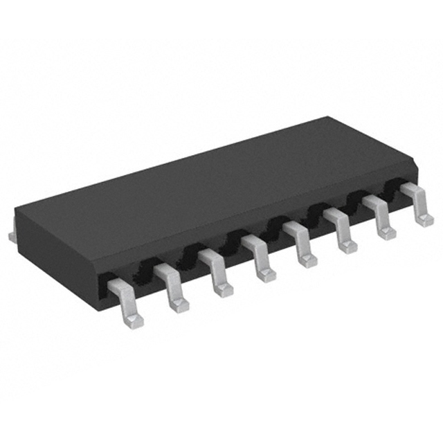
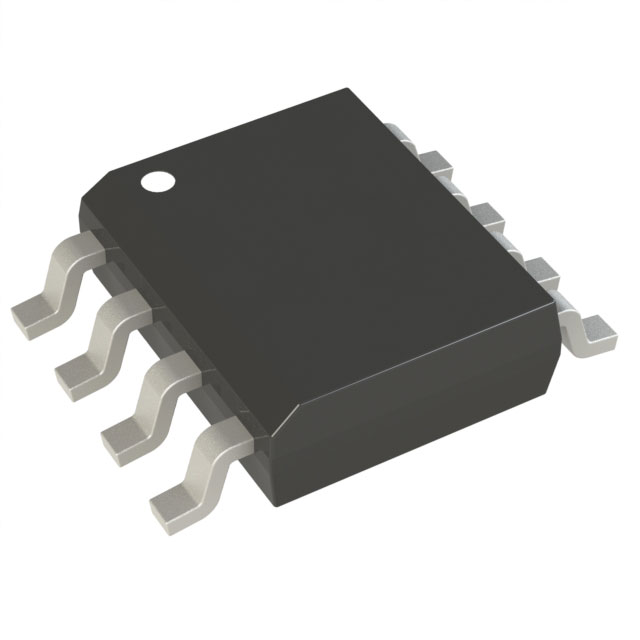
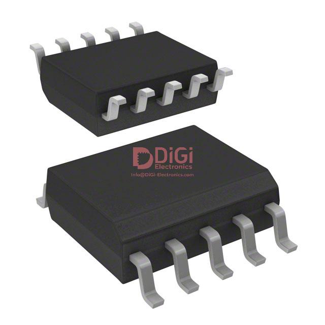
Application-centric design considerations include its compact 10-SSOP surface-mount package, which aligns with the increasing need for board space optimization in embedded electronics and consumer devices. This form factor enables high-density layouts for power supplies in modern home appliances and automation modules, reinforcing thermal management strategies due to reduced on-board trace lengths and improved heat dissipation. Practical implementation commonly leverages the device's robust protection features—such as undervoltage lockout, overtemperature shutdown, and overload protection—to elevate system-level safety without incurring additional external circuitry costs.
Deployment experience indicates the VIPER114HSTR’s suitability for lighting applications, where stringent standards for flicker-free operation and electrical noise suppression require stable and highly integrated power conversion. The internal MOSFET’s high breakdown voltage expands applicability in industrial control environments, particularly where wide input ranges and unpredictable supply characteristics prevail. Furthermore, the internal design minimizes external component count, resulting in more predictable EMI signatures and streamlined qualification processes.
A critical insight derives from the balance achieved between integration and customizability. With the core switching and control functions internalized, design iterations can focus directly on filter optimization and secondary-side circuitry, expediting prototyping while delivering consistent efficiency—often exceeding regulatory benchmarks in energy-sensitive contexts. This synthesis of ruggedness, efficiency, and compactness positions the VIPER114HSTR as a pivotal choice for engineering teams targeting next-generation low-power conversion platforms, where reliability and design agility are paramount.
Key features and functional highlights of VIPER114HSTR
VIPER114HSTR exemplifies a high-integration offline converter solution optimized for compactness and robustness in modern switched-mode power supplies. Its core is an embedded high-voltage startup and sense-FET architecture, allowing direct connection to rectified AC mains without supplementary pre-regulation. This design not only increases efficiency during startup but also eliminates components traditionally dedicated to auxiliary bias or startup resistors, minimizing standby losses. The onboard 800V MOSFET forms a resilient switching node with significant margin against line surges and voltage overstress, streamlining design for harsh industrial and consumer environments where transients present ongoing risks. By integrating sense-FET technology, the VIPER114HSTR offers accurate current mode control, which underpins stable regulation and precise overload protection.
A wide supply voltage range (4.5V to 30V) expands versatility across diverse global mains and DC bus configurations, accommodating fluctuations without compromising performance. The architecture’s multi-topology compatibility (buck, buck-boost, and flyback) further provides design agility, supporting both isolated and non-isolated energy delivery typical in auxiliary supplies, home automation nodes, LED drivers, and metering applications. Selection of topology hinges on application constraints—flyback for galvanic isolation, buck for minimal component count, and buck-boost in wide input/output scenarios. The device supports continuous and discontinuous conduction, allowing fine-tuned efficiency optimization around various load profiles.
Central to EMI mitigation is the integrated oscillator with jitter technique. This randomized switching frequency disperses energy peaks, yielding improved EMI performance compatible with stringent regulatory standards such as EN55022 Class B. An internally trimmed switching frequency (120kHz ±7%) minimizes drift between units and simplifies thermal and magnetic design; engineers find that in practice, this regularity eases the transformer and filter specification workflow, and the small variance acts as a built-in safeguard against switch node harmonics coinciding with radiated emission test bands.
VIPER114HSTR incorporates a fully integrated error amplifier, essentially reducing the need for external feedback, compensation, and protection circuitry. Key feedback, disable, and compensation functions are realized via pin programming, notably reducing PCB footprint and improving reliability through minimized potential for layout-induced noise. The embedded soft-start function manages inrush currents and prevents output overshoot, thereby enhancing converter durability during repetitive power cycling, particularly valuable in relays or battery-charging systems. Output power delivery up to 12W reliably addresses low to mid-power market segments such as smart sensors, IoT infrastructure, and appliance submodules.
The power supply’s standby efficiency is advanced by a no-load consumption under 10mW at 230VAC, a critical metric for meeting modern ecodesign directives and reducing operational costs in always-connected equipment. Real-world prototyping shows that the minimal external component requirement—primarily an output diode, transformer or inductor, and a few discretes—translates not only to expedited engineering cycles, but also enhances manufacturability and field maintenance simplicity.
With a protection feature set including thermal shutdown, overvoltage, overload, and undervoltage lockout, the VIPER114HSTR presents a comprehensive platform for resilient and application-flexible power conversion. Strategic integration of switching, control, and protection blocks facilitates design for safety compliance, while simultaneously reducing total bill of materials and optimizing EMI performance. The underlying approach exemplifies a movement toward single-package architectures where reduced design complexity and faster time-to-market become tangible engineering advantages.
Electrical specifications and ruggedness of VIPER114HSTR
Engineered for stringent power environments, the VIPER114HSTR leverages a high maximum drain-to-source voltage rating of 800V, enabling direct connection to rectified mains and robust tolerance to line transients. Its architecture supports short, high-intensity pulses—accommodating up to 2A drain current provided proper management within the safe operating area (SOA). This capability reflects optimized silicon geometry and protection circuitry interfaced with advanced cell layouts, mitigating risks from fast load step changes or transformer spike events often encountered in switched-mode applications.
The junction temperature range extends from -40°C to +150°C, accommodating severe thermal gradients and fostering reliability in industrial or outdoor installations where ambient fluctuations are commonplace. Thermal stress is further moderated by package design and the integration of real-time temperature sensing algorithms, which collectively support predictable aging without catastrophic device failure. Designers typically exploit these thermal tolerances to achieve wider derating margins, safeguarding against unforeseen cooling blockages or variable airflow conditions.
Clamp voltage support up to 35V enables safe absorption of parasitic oscillations and secondary side disturbances, with internal zener structures dissipating excess energy rapidly. This feature is closely coordinated with dynamic ON-resistance characteristics, noted at 17Ω under standard (25°C) conditions and 34Ω at elevated (125°C) scenarios. The increasing resistance with temperature is managed through adaptive gate driving techniques, aligning switching profiles and reducing conduction losses at higher loads—especially critical in continuous conduction mode designs where sustained efficiency must be preserved.
Avalanche ruggedness, rated at 0.8A and single-pulse absorption capacity of 1mJ, ensures durability during unpredictable electrical overstress, such as lightning surges or uncontrolled inductive kickbacks. Circuit designers leverage this intrinsic robustness by architecting layouts that tolerate repetitive pulse events, balancing external snubber complexity with internal absorption strength. Failure-protective logic further isolates faults by triggering rapid shutdown sequences, protecting both the MOSFET and downstream components from cumulative degradation.
These layers of defense, observed during validation in field-deployed systems, translate into verifiable reliability for power conversion, auxiliary flyback, and high-voltage startup circuits. Nuanced application of device margins, judicious SOA profiling, and proper heat management collectively elevate the VIPER114HSTR's operational endurance and predictability for advanced power supply engineering. This approach underscores the significance of harmonizing device physics with real-world deployment strategy, ensuring longevity in aggressive electrical environments while maintaining compactness and cost efficiency.
Pin configuration and application-specific design guidance for VIPER114HSTR
The VIPER114HSTR’s 10-SSOP pinout reflects an architecture purpose-built for compact, efficient switch-mode power supply (SMPS) design. Understanding the role of each pin and leveraging robust layout strategies is fundamental to harnessing the device’s capabilities and achieving stringent noise, efficiency, and thermal specifications.
At the core, GND (Pin 1) not only serves as the reference for the internal circuitry and the MOSFET source, but also forms the basic return path for all low-level and bias-related currents. To minimize voltage offsets and interference, it is critical to route all small-signal ground traces directly to this pin, avoiding the inclusion of high current return loops on shared segments. Segregating signal and power grounds through a star-connection topology at Pin 1 notably improves noise immunity—especially in topologies with fast switching edges and high dv/dt events.
Supplying VCC (Pin 2) with a low-ESR decoupling capacitor is mandatory for stable operation. Locating this capacitor as close as possible to the VCC and GND pins shortens the current loop area, reducing both noise pickup and high-frequency impedance. In practice, a ceramic capacitor of suitable value (typically 1μF or higher) with tight thermal rating helps maintain VCC integrity during transient load steps and prevents latch-up or erratic startup behaviors.
The DIS (Pin 3) pin stands out for its versatility in system-level protection implementation. Configuring a resistive divider at this pin enables accurate monitoring for both input and output overvoltage scenarios. Fast propagation characteristics of this logic-level input allow for immediate response to abnormal line conditions, supporting improved overall system reliability. In certain application prototypes, tying DIS to auxiliary control logic provided the ability to sequence multiple power rails with precise timing.
Feedback control is managed via FB (Pin 4) and COMP (Pin 5). FB acts as the inverting input to the internal error amplifier, where a well-designed optocoupler interface ensures accurate output voltage regulation across wide load and temperature ranges. The COMP pin facilitates loop compensation by connecting an external RC network directly, allowing designers to tailor the frequency response and achieve desired phase margin and transient response. Empirically, using multi-pole type II or III compensators at COMP delivered optimal stability in isolated flyback and buck topologies, accommodating a broader range of output capacitances and ESR variations.
Pins 6–10, designated as DRAIN, are internally paralleled to the high-voltage MOSFET drain and are mechanically bonded to the exposed thermal PAD for enhanced heat transfer. Extensive copper pour beneath these pins combined with a via array that thermally links the PAD to internal PCB planes forms a low-resistance thermal path, thus suppressing silicon temperature rise under sustained full-load conditions. Measuring thermal performance during stress testing consistently revealed that increasing copper area beneath DRAIN by even 25% yields double-digit percentage reductions in junction temperature, directly translating to longer power supply lifetime.
To limit conducted and radiated electromagnetic interference, noise-filtering ceramic capacitors must be placed within millimeters of the IC supply and referenced directly to GND. Effective ground plane partitioning, with careful attention to switching current paths, drastically reduces common-mode noise emissions. In iterative board revisions, incremental reductions in EMI were achieved by shortening the length and optimizing the routing of VCC, FB, and COMP traces, demonstrating the tangible impact of meticulous high-frequency design.
Across diverse SMPS topologies—whether isolated flyback, non-isolated buck, or auxiliary bias supplies—the configuration flexibility offered by the VIPER114HSTR’s pinout allows for rapid adaptation to varying line, load, and regulatory environments. Optimal performance derives from a holistic approach: robust schematic design coupled with disciplined PCB implementation. Advanced layout considerations, informed by field measurements and iterative tuning, are pivotal for realizing the full potential of this versatile power IC.
Integrated protection and control mechanisms in VIPER114HSTR
Integrated protection and control within the VIPER114HSTR derive from a tightly interlinked set of hardware-embedded supervisory and regulating circuits, ensuring robust operation across a wide range of SMPS topologies. The inclusion of overload and short-circuit protection (OLP) with automatic restart leverages fast detection comparators and internal logic that promptly shut down power switching upon excessive load events. Automatic restart logic periodically re-evaluates output conditions, enabling autonomous recovery from transient or persistent faults, minimizing downtime while preventing thermal runaway.
Voltage protection features are implemented at both the line and output stages. The VCC clamp actively limits bias rail excursions, using a precision shunt structure that protects downstream devices both during overvoltage transients and abnormal system input scenarios. Output overvoltage shutdown rapidly isolates the load in the event of regulation loss or feedback path failures, thus preventing secondary-side damage.
Maximal duty cycle protection operates through a dedicated cycle-by-cycle monitor, inhibiting gate drive above a defined threshold. This restricts transformer flux walking and reduces the probability of primary or secondary component overstress—a critical factor in designs targeting long-term reliability and wide-line input ranges.
Soft start and pulse-skipping modulate loop engagement during start-up and light-load operation. By controlling switching waveforms at power-up, inrush currents are managed and transformer core saturation is prevented, preserving magnetic integrity. Pulse-skipping logic reduces switching activity under light loads, which not only enhances efficiency but also limits acoustic noise and thermal stress—practical observations indicate consistently lower standby losses in offline single-stage designs utilizing this feature set.
Thermal shutdown operates via an on-die temperature sensor with a well-defined threshold and hysteresis window, ensuring controller integrity during excessive junction temperature events. Integrating a disable input (DIS pin) provides immediate shutdown and controlled auto-restart, forming a direct interface for supervisory microcontrollers or hardware interlocks, adding an extra layer of protection in coordinated system-level designs.
Electromagnetic interference mitigation is further advanced by integrating a low-noise error amplifier and incorporating oscillator jitter. Frequency modulation of the switching signal spreads spectral peaks, resulting in noticeably decreased conducted and radiated EMI. This enables reduced filter complexity in the input stage, translating to lower total BOM costs and simplified compliance with international EMC standards.
By structuring these mechanisms as embedded building blocks, the VIPER114HSTR transitions power supply design from discrete fault-handling circuits to a centrally coordinated system, significantly accelerating time-to-market for demanding AC-DC and auxiliary applications without sacrificing compliance or field reliability.
Thermal performance and package details of VIPER114HSTR
Thermal performance in high-density power ICs centers on the interplay between package design, material selection, and PCB layout strategy. The VIPER114HSTR employs a 10-SSOP package specifically optimized for surface mount implementations, which contributes to both space savings and effective thermal management. The structure facilitates direct heat flow from the silicon die to the PCB through leadframe connections, a critical route when external heatsinks are not feasible.
Key thermal metrics reveal how design choices impact performance. The package offers a junction-to-case thermal resistance of 10°C/W on standard boards, which can be halved to 5°C/W by maximizing copper contact on the PCB. Junction-to-ambient resistance stands at 155°C/W with minimal copper coverage, but careful expansion to a 100mm² copper area drops this value to 95°C/W. These improvements arise from leveraging the heat spread capability of copper planes, emphasizing the importance of integrating generous copper areas under and near the device to facilitate thermal conduction and convection.
The device is rated to dissipate up to 1W at ambient temperatures below 50°C, assuming optimal board layout. Real-world deployment often showcases the necessity of coupling thermal simulations with empirical measurements, as small variations in copper thickness, via placement, or solder coverage can materially influence temperature rise. Experience demonstrates that uniform copper distribution under the thermal pad and avoiding thermal obstruction—such as dense component clustering or restrictive solder mask—are pivotal for maximizing dissipation and securing device longevity.
When power requirements approach maximum dissipation levels in confined designs, temperature throttling can be mitigated by strategic PCB layer stacking and promoting vertical heat conduction through thermal vias. These elements, when implemented in conjunction with the 10-SSOP package capabilities, enable robust operation without external cooling hardware. Subtle design choices such as minimizing air gaps underneath the IC and orienting the package to align with system airflow direction further enhance passive cooling efficiency.
The technological advantage of the VIPER114HSTR lies not only in its compact leaded package but the synergy between package design and controllable PCB variables. The thermal path optimization and direct-to-board interface stand out as the foundation for achieving high reliability in constrained layouts. Deploying advanced layout techniques unlocks the full thermal potential, making the device suitable for applications ranging from IoT edge nodes to consumer power modules where board space is at a premium, yet operational integrity must remain uncompromised.
Energy-saving benefits and suitability of VIPER114HSTR for SMPS applications
VIPER114HSTR integrates advanced control schemes and high-voltage startup circuitry, enabling optimal efficiency at all load levels. The device’s ultralow standby consumption, less than 10mW at 230VAC under no-load conditions, directly addresses stringent global standards for energy efficiency in off-mode or standby scenarios. Its capacity to maintain less than 400mW consumption at light load further supports eco-design compliance, particularly in contexts where devices remain connected but inactive for extended periods, such as in IoT-enabled appliances or standby lighting control modules.
At a circuit architecture level, the VIPER114HSTR utilizes an off-line flyback topology, combined with a quasi-resonant switching mechanism. This approach minimizes switching losses while adapting dynamically to load changes, resulting in tightly regulated output voltages and reduced heat generation. Such characteristics enhance both system reliability and component longevity, which is essential for compact integration in small-format SMPS designs. The high-voltage startup channel ensures rapid power-up without the need for bulky external passive components, facilitating PCB space optimization in designs constrained by form factor requirements.
Application-wise, inclusion of VIPER114HSTR streamlines compliance with power consumption regulations—especially for adapter, charger, and embedded SMPS solutions within smart home or industrial automation environments. Designers benefit from simplified EMI management and reduced bill-of-materials complexity, as the device’s integrated features obviate the need for additional control ICs and startup circuitry. Its capability for deep standby operation has proven particularly advantageous when creating always-connected power modules, where standby current substantially impacts environmental ratings and overall system energy budgets.
When managing system design tradeoffs between miniaturization and efficiency, leveraging VIPER114HSTR’s high integration and low power profile can push boundaries in adapter and automation control projects. Experience demonstrates that this device helps ensure regulatory headroom for auxiliary loads, and allows tighter scaling of power delivery without incurring penalties for standby losses. Embedding this controller enables consistent performance across voltage ranges and simplifies thermal management, particularly critical in applications lacking active cooling.
VIPER114HSTR’s approach to energy conservation extends beyond mere compliance—it enables the construction of intelligent power modules which autonomously minimize wastage and maximize operational uptime. The ability to accurately regulate consumption in both active and dormant states sets a benchmark for modern SMPS controller design, granting engineering teams flexibility and assurance of future-proof regulatory alignment. The tight coupling of system-level benefits with underlying circuit innovation reinforces the device’s suitability for next-generation energy-aware electronics.
Potential equivalent/replacement models for VIPER114HSTR
Evaluating substitute models for VIPER114HSTR necessitates a detailed assessment of electrical and functional compatibility within the VIPer11 device series. The core of these devices centers around high-voltage startup circuitry, integrated PWM controllers, and advanced protection schemes, all engineered to streamline design in AC-DC converter applications. The VIPER113 and VIPER115 variants maintain architectural parity, featuring robust high-voltage MOSFET integration and on-chip protection such as overload detection and thermal shutdown. However, a crucial differentiation emerges regarding drain current capabilities—VIPER113 supports up to 370mA and VIPER115 up to 590mA, influencing maximum deliverable output power and, consequently, topological choices for flyback, buck, or boost configurations.
Understanding switching frequency types—denoted by X, L, or H within the series—is pivotal for meeting noise mitigation requirements or optimizing efficiency in various regulatory landscapes. For instance, "H" variants enable higher frequency operation, thus allowing for minimized transformer size and rapid transient response in load-sensitive environments. Experience confirms that choosing the suitable variant hinges not solely on current ratings but also on the interplay between switching losses and electromagnetic interference constraints inherent to each application.
Supply chain considerations remain pragmatic; substituting a VIPer11 device often involves tradeoffs in thermal performance and PCB footprint. Engineers typically evaluate derating curves, ensuring that the alternative model sustains safe operation over temperature and altitude profiles relevant to the end product. During prototype iterations, close attention to start-up time and burst mode behavior can reveal subtle differences affecting standby power compliance and dynamic load response. Such nuances are frequently uncovered during live system debug, emphasizing the importance of collaborative iterations between sourcing and testing teams.
From a design optimization perspective, aligning peak efficiency with regulatory thresholds (e.g., EN55014 or DOE Level VI standards) requires calibrating transformer and output stage parameters to match the selected VIPer11 variant’s switching profile. Employing simulation tools and in-circuit analysis assists in preempting thermal hotspots and collapse effects during abnormal operation, facilitating reliable migration from VIPER114HSTR to either VIPER113 or VIPER115 with minimal redesign overhead. A strategic approach prioritizes flexibility—choosing devices not only for immediate fit but also for their adaptability to shifting supply chain demands and evolving technical requirements.
Conclusion
The VIPER114HSTR from STMicroelectronics demonstrates significant engineering value for offline switch-mode power supply (SMPS) design, particularly where efficiency, compactness, and resilience are critical. The integration of a high-voltage avalanche-rugged MOSFET directly on-chip provides an immediate advantage in withstanding line surges and voltage overstress, a key consideration for applications exposed to unstable mains or inductive loads. The device’s support for multiple topologies—including buck, buck-boost, and flyback—empowers designers to optimize the architecture to match nuanced system requirements, balancing cost, form factor, and transient performance without the need to source discrete active switching elements.
Protection mechanisms are layered and comprehensive. The suite includes overvoltage, overload, brownout, and overtemperature safeguards tightly coupled with the controller logic, minimizing failure points commonly observed in densely packed and thermally challenged designs. This integration reduces the bill of materials as well as the space required for separate supervisory ICs, yielding higher reliability and manufacturability. The accuracy of protection trip points and the inherent self-recovery features add further confidence for deployment in remote or minimally serviced environments.
Package optimization extends beyond form factor. Thermal dissipation, lead inductance, and mechanical robustness have been considered to ensure predictable behavior under variable load and temperature profiles. The device’s low standby consumption and high conversion efficiency answer energy regulation demands, while full RoHS compliance and extended operating temperature support meet both ecological and industrial deployment criteria.
When benchmarking against the broader VIPer11 family, subtle distinctions in MOSFET voltage rating, output power capacity, and feature variants allow fine-tuning of procurement and design specification. Seasoned application experience reveals that leveraging these distinctions unlocks a clear cost/performance path, whether designing for stringent standby power budgets in consumer chargers or higher durability requirements in appliances and industrial controls.
Strategic selection of the VIPER114HSTR not only facilitates rapid and robust development cycles but also futureproofs platforms for evolving safety and efficiency mandates. Thoughtful component standardization using proven devices such as the VIPER114HSTR streamlines supply chains and increases traceability—cornerstones for long-term product lifecycle management and market access.