 >
>


Product overview: LED5000PHR from STMicroelectronics
The LED5000PHR from STMicroelectronics is a monolithic step-down DC-DC converter optimized for high-brightness LED applications requiring rigorous current control up to 3A DC. Integrating an advanced peak-current mode controller operating at a fixed 850 kHz frequency, the device realizes fast transient response and precise current regulation. Its architecture supports a wide input range from 5.5V to 48V, thus accommodating diverse power sources common in industrial automation, outdoor illumination systems, and architectural lighting.
At the core, the LED5000PHR employs a constant-current buck topology. This structure enables direct regulation of LED drive current, ensuring uniform light output and extended LED lifespans. High switching frequency minimizes external passive component dimensions, yielding space-saving designs critical for dense or thermally constrained layouts. Robust linear and PWM dimming interfaces further provide seamless control over light intensity, facilitating both energy efficiency and sophisticated dynamic lighting effects without compromising color fidelity. The embedded peak-current mode feedback enhances loop stability, especially relevant in designs with variable input voltages or multiple paralleled converters.
Thermal management is integral to high-power LED scenarios. Here, the 8-lead HSOP package incorporates a thermally efficient footprint supporting effective heat dissipation. This, paired with high converter efficiency, supports junction temperature control, thereby improving long-term system reliability. In application, it is observed that careful PCB layout—such as minimizing input loop areas and providing ample thermal vias under the HSOP pad—directly lowers EMI and enhances overall converter resilience in electrically noisy environments.
Protection functions, including programmable soft-start, overvoltage protection, short-circuit safeguards, and thermal shutdown, form a safety net, addressing fault or overload events often encountered in industrial environments. The expansive feature set eliminates the need for external supervisory circuits seen in less integrated solutions, reducing both bill-of-materials costs and board complexity.
In lighting infrastructures where scalability and modularity are paramount, the design flexibility offered by the LED5000PHR's wide input range and precise dimming capabilities translates into rapid adaptation—one driver fits multiple deployment models. System designers consistently benefit from the predictable regulation behavior under wide voltage swings, which is especially valuable when integrating emergency backup supplies or solar-powered installations.
Exploring the interaction between switching frequency, output ripple, and component sizing reveals nuanced trade-offs. High-frequency operation, while reducing magnetic component bulk, demands scrutiny of EMI compliance and careful snubber or filter selection to ensure system-level certifications. Empirical tuning of output capacitors or selection of shielding inductors often proves decisive in meeting stringent end-market electromagnetic standards.
The LED5000PHR is positioned as an agile core for LED-based lighting solutions where efficiency, flexibility, and robustness drive value. Its detailed integration shortens development cycles and raises project predictability, making it a preferred component in both new designs and retrofit applications targeting long-term performance and maintainability.
Key features and application scope of LED5000PHR
The LED5000PHR exemplifies a high-efficiency, fully integrated LED driver, optimally designed for mission-critical lighting infrastructures where reliability, precise control, and scalability are essential. At the silicon level, its architecture leverages a peak current mode control scheme, which inherently stabilizes the current loop across wide input voltages and rapidly changing transient conditions. This architecture proves particularly effective in outdoor environments where mains supply fluctuations and ambient temperature shifts are routine.
The extended input range (5.5V to 48V) enables seamless compatibility with diverse power sources, from battery-backed systems to standard AC/DC adapters. This flexibility underpins use cases such as street luminaires, digital signage, and emergency light fixtures. Deployments benefit from simplified bill-of-materials management, as board designers need not customize circuits for each application voltage domain.
Output current regulation is maintained with ±3% accuracy across the operating temperature spectrum, ensuring color consistency and lumen stability—a necessity in architectural illumination or museum-grade spotlighting. Experience shows that fine current regulation also facilitates precise matching of multi-channel arrays in facade lighting, minimizing perceptible variance across zones. The adjustable 3A ceiling supports high-power LED modules, meeting the thermal and brightness demands of retrofits replacing halogen solutions.
The device’s 850 kHz maximum switching frequency stands out, directly shrinking passives and minimizing PCB real estate. Compatibility with ceramic output capacitors enables tighter designs with superior ripple performance. This, coupled with the low RDS(ON) internal FET (typ. 200 mΩ), provides conversion efficiency profiles exceeding 90% in common setups for streetlight and advertising panels, lowering overall system heat and relaxing heatsink requirements.
Topology flexibility—support for buck, buck-boost, and floating boost arrangements—addresses complex lighting grids featuring mixed-voltage strings or variable LED forward voltages. Floating boost topology, for example, finds utility in retrofit scenarios requiring isolated output rails, while buck-boost implementation is pivotal in battery-powered mobile signage facing broad voltage sags.
Dimming control is streamlined via standard PWM input, facilitating granular brightness management and integration with smart control protocols or occupancy-sensing schemes. High-resolution PWM minimizes flicker and ensures smooth transitions, critical in retail and hospitality installations where lighting quality impacts customer perception. Field experience demonstrates stable operation down to sub-1% duty cycles, accommodating advanced fade and scene-setting requirements.
Comprehensive protection features—thermal shutdown and robust short-circuit handling—enable long-term deployment in environments prone to overcurrent events and high ambient temperatures. The low standby current (inhibit <40 μA) proves beneficial for solar-powered installations and smart city deployments, where standby losses compromise overall energy conservation efforts.
Biasing the design towards high integration, the LED5000PHR reduces external parts count, enhancing assembly reliability and cost competitiveness. Its layered protection mechanisms permit tighter spec adherence under varying load profiles, supporting lighting systems that must operate continuously with minimal intervention.
A core insight informed by hands-on prototyping is the balance it strikes between configurability and control precision: advanced users can direct the topology and dimming scheme to suit intricate requirements, yet the inherent stability and protection means out-of-the-box configurations work reliably even in less-controlled environments. This duality catalyzes rapid deployment and scalable lighting innovation across urban, industrial, and specialty contexts.
Electrical characteristics and functional description of LED5000PHR
The LED5000PHR operates as a high-performance LED driver IC centered around a robust peak-current mode control architecture. Its fixed switching frequency underpins fast transient response and consistent output regulation—qualities essential for lighting applications with dynamic loads or fluctuating input voltages. The core mechanism employs a low-noise precision voltage reference, buffered by an integrated pre-regulator stage for immunity to supply disturbances. This establishes a highly stable control baseline, forming the bedrock for reliable LED current regulation even in noisy or unstable environments.
A key innovation within the signal chain is the transconductance error amplifier, configured to interface directly with a high-side current sense amplifier. This topology enables precise sensing of the output current through a low-value external resistor, typically referenced at 200 mV. By targeting this low differential, conduction losses are reduced, enhancing both efficiency and thermal performance. Moreover, high-side sensing accommodates common anode or cathode arrangements, simplifying system integration and expanding compatibility with diverse LED string configurations. The feedback loop is carefully compensated to maintain bandwidth, preventing overshoot during rapid dimming transitions and load steps.
Soft-start circuitry is optimized to shape input current and limit voltage overshoot during initial power-up. This approach not only mitigates stress on both the power switch and LED elements but also reduces electromagnetic interference typically associated with inrush events. The soft-start ramp can be tailored externally, accommodating a wide range of application-specific startup profiles. Complementing this, an advanced PWM dimming block operates independently of the device’s startup sequence, fully decoupling dimming fidelity from power supply transients. This decoupling translates to uniform dimming response across the full brightness range, realizing high color rendering and eliminating perceptible flicker—an aspect critical for architectural illumination and demanding display backlighting.
For power-sensitive systems, the integrated inhibit logic enables seamless transition into ultra-low-power standby modes. By dynamically shutting down nonessential analog blocks, quiescent current is minimized without compromising startup readiness. Protection features are deeply embedded, providing immediate pulse-by-pulse current limiting on short transients, escalating to full hiccup-mode fault management under persistent overload or thermal stress. This layered scheme enhances both safety and long-term reliability in field deployments, as observed in installations subjected to frequent voltage irregularities.
The architecture’s flexibility extends to its application scope, supporting a range of external power stage configurations including buck, boost, or SEPIC topologies. Component selection at the switching node affords fine control over switching frequency, loop dynamics, and EMI profile—parameters that can be tuned to align with regulatory standards or proprietary industry requirements.
Observations in complex lighting installations highlight the value of the IC’s immunity to supply noise and the consistency of dimming performance, even when subjected to harsh mains variation or frequent mode transitions. These real-world scenarios underscore the practical advantage of the device’s tightly integrated protection and feedback elements, reducing field support requirements and enabling rapid design cycles. A subtle but consequential insight is the synergistic effect of pairing high-side current sensing with finely grained PWM dimming; this combination executes precise brightness control without introducing thermal drift or color shift, a demand often overlooked in high-reliability lighting applications.
In summary, the LED5000PHR embodies a balance between precision current regulation, rugged fault tolerance, and versatility in system integration, supporting stringent lighting requirements from automotive to industrial environments. The architecture’s layered protection, control, and feedback results in a platform capable of delivering both performance and resilience under a diverse range of real-world operating conditions.
Design considerations for LED5000PHR: Buck and alternative topologies
When evaluating the LED5000PHR for LED current source applications, the device’s foundational architecture must be examined through the lens of conversion topology and robustness under varying electrical contexts. Primarily architected for buck (step-down) operations, the LED5000PHR integrates internal circuits facilitating high-efficiency direct current regulation—an imperative for meeting stringent LED luminance and reliability requirements. The control loop is accessible and highly customizable, with detailed guidance in semiconductor literature for error amplifier compensation and frequency response alignment. Engineers should approach loop optimization as an iterative process: response time and output ripple are tightly intertwined with system bandwidth and compensation poles/zeros, thus balancing transient performance against electromagnetic interference becomes a core exercise in filter selection and loop shaping. For fine-tuning, empirical placement of a low-ESR ceramic output capacitor alongside careful inductor selection (<30% ripple current ratio) consistently yield superior current regulation and reduced luminous flux variation during PWM dimming cycles.
The adaptability of the LED5000PHR for inverting buck-boost, positive buck-boost, and floating boost increases its value in systems where supply voltage transitions above and below the LED string voltage, or where multiple current domains must be orchestrated. These alternative topologies introduce additional boundary conditions; specifically, switch selection must account for bidirectional voltage stress, and peak inductor current can substantially exceed average values, necessitating components rated for transient stressors. The circuit’s feedback path, inherently more complex in non-buck modes, demands tight PCB layout and precision divider networks to prevent offset drift and tolerance-induced overcurrent or flicker. Practical deployment in floating boost topologies reveals that synchronous rectification and snubber networks are often mandatory to maintain conversion efficiency and suppress high-frequency ringing.
Rigorous evaluation of protection features—such as overvoltage, short-circuit, and open LED safeguards—should be explicit in the schematic phase, particularly for systems scaling to multiplicity in string count or thermal junction stress. Layering the control and protection loops minimizes fault propagation, a design tenet validated in distributed lighting installations subject to variable load and supply conditions.
From a broader systems perspective, the implicit insight is that topology selection should be driven not by controller topology agnosticism, but through a holistic assessment of the interaction between LED characteristics, thermal environment, and application-specific reliability. The LED5000PHR’s flexibility is best leveraged when engineers integrate holistic bench validation—oscilloscope monitoring of current waveforms during fault insertion and drive signal modulation—into the design cycle. This fosters a calibration mindset, enabling robust solutions that withstand real-world perturbations and operational stress.
Component selection guidelines for LED5000PHR
In implementing LED5000PHR systems, precision in passive component selection underpins both electrical stability and application efficacy. The sensing resistor, a pivotal element in current regulation, demands calculation aligned to output specifications. Utilizing the formula Rs = 200mV / ILED ensures tight control over the maximum allowable current, directly affecting LED longevity, spectral stability, and thermal management envelope. Selection should account for tolerance, temperature coefficient, and pulse handling capability, as even micro-ohm discrepancies or inadequate surge endurance can propagate into inconsistent luminance or premature failure.
The inductor and output capacitor must be dimensioned in concert to constrain LED current ripple within acceptable bounds (≤0.5 × ILED), safeguarding against visible flicker and color shift. Lower inductance and capacitance values accelerate dimming dynamics, critical in displays and automotive signaling. However, engineering trade-offs arise: reduced values heighten ripple amplitude and EMI susceptibility, necessitating detailed loop analysis and, often, simulation to assess transient behavior. Selection of ferrite-core inductors with predictable saturation characteristics and capacitors with stable capacitance across temperature and bias enhances reliability in high-pulse environments.
Input capacitor choice is frequently underestimated in its system-wide impact. Capacitors should exhibit low ESR to suppress voltage deviations during switch transitions, with ripple current ratings exceeding anticipated peaks. Ceramic capacitors, preferably X7R or C0G types, deliver robust impedance performance up to several megahertz and withstand voltage overshoot stemming from load dump or supply surge. Sizing must incorporate layout constraints and account for possible derating under sustained high-frequency operation; insufficient input capacitance can inject oscillatory noise throughout the circuit and compromise EMI compliance.
A carefully architected compensation network anchors system stability, dictating bandwidth, phase margin, and dynamic response under load step or PWM dimming. Targeting a crossover frequency near fSW / 6 balances noise immunity against transient agility, enabling rapid and distortion-free current modulation. Calculation leverages small-signal models, with real-world fine-tuning informed by oscilloscope sweeps and bandwidth margining, optimizing loop characteristics for multifaceted demands—from static arrays to systems enforcing millisecond-scale current pulsing in demanding visual or medical applications.
Across varied configurations, component selection must bridge theoretical modeling and practical realities, integrating board layout, thermal management, and regulatory compliance. Insight emerges that expansive simulation, coupled with iterative bench validation, best reveals parasitic interactions and dynamic deficits. Rather than generic parts, leveraging application-specific passive selections tightens control and cultivates scalable, reproducible outcomes—elevating device integrity in both commodity and critical-use LED deployments.
Layout and thermal management in LED5000PHR-based designs
Effective PCB layout and advanced thermal management are paramount in designs employing regulators like the LED5000PHR, whose high-switching operation introduces both electromagnetic noise and localized heat concentrations. Optimal performance hinges on rigorous control of both electrical and thermal behaviors, starting at the layout level.
Precise routing is the first line of defense against noise and emission issues. High-current loop areas, typically around switching nodes and critical input/output traces, must be systematically minimized. Compact return paths for these loops directly reduce radiated and conducted EMI. For switching converters, the input capacitor should be placed as close as possible to the device VIN and power ground pins, eliminating loop inductance and associated voltage spiking. The feedback network, sensitive to voltage fluctuations, benefits from shortest and most direct routing to the sense resistor—shielding this path from neighboring power traces and fast-switching nodes prevents inadvertent coupling of high-frequency noise, which in practice is a frequent root of unstable regulation or degraded transient behavior.
Thermal optimization is not merely a matter of heatsink selection—it begins at ground plane architecture. The HSOP8 package's exposed thermal pad, when soldered onto an unbroken analog ground plane, ensures efficient conduction of heat from die to board. This contiguous copper also forms the electrical reference, tying together analog sections for signal integrity. Separation of power and signal grounds is essential to preventing common-mode disturbances, but must be resolved by a single, low-impedance connection—ideally located directly under the output capacitor where switching currents are lowest and voltage is most stable. Trace width selection for power paths warrants attention as well; in scenarios with sustained high load, generous copper pours and strategic via stitching dramatically improve both current carrying capacity and spreading of thermal energy. Observations in the field indicate that insufficient copper beneath the device can push local temperatures out of bounds, accelerating device degradation or triggering protective shutdowns.
Accurate estimation of power losses is indispensable in predicting thermal margin. Conductive losses, tied to both inductor resistance and device on-time, and switching losses, scaling with frequency and voltage swing, aggregate with the device's quiescent draw. Using the specified junction-to-ambient thermal resistance (around 40°C/W for HSOP8), one can project temperature rises under worst-case scenarios. For example, a converter providing 1.5A at 42V routinely operates near thermal limits if copper area is restricted to minimal datasheet recommendations. In demanding deployments—such as automotive or industrial lighting where ambient conditions are harsh—expanding the ground plane footprint or coupling to external heatsinking pads is non-negotiable. Empirical exploration reveals that doubling the copper area or integrating additional vias to rear-side planes can halve temperature rise, greatly enhancing reliability over the operational lifespan.
Ultimately, high-efficiency, robust LED power delivery is realized through disciplined attention to both thermal and electrical layout principles. Integrating advanced simulation tools early in the process further streamlines design iteration, allowing rapid convergence on layouts that meet performance, safety, and emission targets without overdesign or excessive cost. Embedded within these practices is an appreciation for the intertwined nature of electrical noise and thermal flow—the architectural decisions made at layout stage form the bedrock for both regulatory compliance and dependable system operation.
Protection mechanisms and reliability in LED5000PHR
Protection mechanisms in the LED5000PHR are constructed with an emphasis on fault tolerance and operational continuity, reflecting a multilayered design strategy. At the core, the device implements pulse-by-pulse current limiting, which operates as an immediate first line of defense against short-circuit and overcurrent faults. This mechanism constrains the switching current during each cycle, enforcing a minimum conduction period that avoids excessive energy delivery even during transient overloads. When conditions persist beyond normal mitigation thresholds, the circuit transitions to hiccup-mode—periodically suspending and restarting operation. This significantly reduces both average power dissipation and peak thermal exposure, minimizing the likelihood of device or load failure. Such an approach is often observed to substantially extend system survivability during downstream short circuits, with repeated, automatic recovery cycles obviating manual intervention.
Thermal protection is achieved with a dedicated shutdown circuit that monitors the internal junction temperature with relatively tight hysteresis. The controller disables switching activity once the thermal threshold, typically set at 150°C, is surpassed. This proactive interruption continues until sufficient cooling is detected, at which point regular operation resumes. In complex board-level implementations, effective layout and thermal coupling enhance the responsiveness of this mechanism, yielding quick system recovery after thermal excursions while shielding the IC and surrounding components from cumulative degradation effects.
Overvoltage protection extends to scenarios such as open-LED conditions, where an interrupted LED string risks exposing both the driver and surviving components to abnormal voltages. Here, the architecture accommodates external circuitry—commonly realized with a Zener diode in series with a resistor. This configuration clamps the output voltage, absorbing excess energy and maintaining device integrity. Design optimization typically involves careful selection of the Zener breakdown threshold, factoring in worst-case load disconnect conditions and the permissible maximum voltage ratings of both the LED string and drive circuitry.
Field applications often underscore the practical value of these protections. For instance, installations subject to frequent mains disturbances or inductive load switching benefit from the combination of rapid overcurrent limiting and automatic thermal recovery, which together avert service interruptions and reduce maintenance demands. Furthermore, integrating adjustable thresholds—where permissible—enables fine-tuning for distinct load types or environmental constraints, providing both flexibility and enhanced reliability margins.
The holistic inclusion of hardware-based safety features—complemented by thoughtfully designed external components—demonstrates a philosophy oriented towards autonomous fault management. Such integration minimizes reliance on ancillary supervision while adapting to evolving operational risks. This layered approach not only strengthens system robustness under foreseeable hazards, but also introduces latent resilience against atypical stressors, reinforcing confidence in deployment across demanding power or harsh ambient conditions.
Package information and integration notes for LED5000PHR
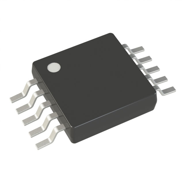
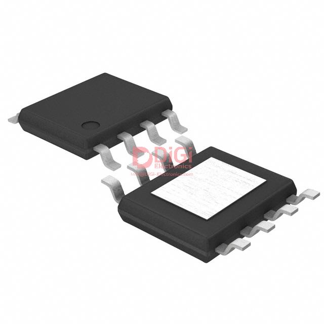
The LED5000PHR is housed in an ECOPACK®-certified HSOP8 package, engineered to meet stringent environmental standards and offered in both leaded and lead-free configurations. Central to its thermal management strategy is an exposed pad on the package underside. Reliable heat dissipation demands this pad be soldered directly to a robust PCB ground plane, establishing a low thermal resistance path and ensuring optimal operational stability under load.
From a mechanical standpoint, the compact HSOP8 profile facilitates high-density component placement, making it attractive in designs where board space is critically limited. The pad’s metallization and placement maximize thermal transfer efficiency only if the adjoining PCB copper area is sufficiently sized and well-connected to the ground network. Shortcomings in pad soldering, such as insufficient solder coverage or weak thermal connections, directly impact device reliability and long-term performance. In practice, precision in reflow parameters and pad stencil design is essential; even slight misalignment can degrade heat sinking capacity and invalidate published package thermal metrics.
Electrically, the ground pad functions as more than a simple thermal feature. In noise-sensitive circuits, this connection curtails parasitic impedance, contributing to improved EMI resilience. When deploying the LED5000PHR in high-density lighting or power regulation modules, careful thermal simulation and layout optimization—emphasizing via arrays beneath the pad—enable prototypes to achieve measured junction temperatures close to simulation predictions, verifying the integration’s efficacy.
Leveraging the ECOPACK® package not only aligns with compliance policies but also streamlines supply chain logistics by offering multi-format options. Integrating the thermal pad with a continuous ground plane is non-negotiable for extracting rated performance, and real-world validation of thermal behaviour often reveals that doubled ground plane area yields even lower operating temperatures than datasheet minimums, especially in multilayer PCBs.
Future-proofing board designs through strategic pad connection layout, standardized stencil apertures, and quality-controlled solder paste deposition emerge as decisive factors. Attention to these integration nuances distinguishes robust assemblies, enabling LEDs and associated drivers to sustain output in demanding environments without thermal-induced derating. For engineers tasked with maximizing throughput and minimizing post-production failures, expertise in package-level thermal design translates directly into system reliability and lifecycle cost reduction.
Potential equivalent/replacement models for LED5000PHR
A comprehensive assessment of equivalent or replacement models for the LED5000PHR requires structured analysis at both the circuit architecture and application integration levels. The LED5000PHR, designed as a high-brightness LED driver, establishes its primary differentiators through an input voltage tolerance reaching 48V, an output current delivery spanning 2–3A, and robust PWM dimming support compatible with multiple switching topologies. Specialized features, such as integrated over-temperature, over-voltage, and short-circuit protections, as well as embedded efficiency enhancement schemes, are pivotal for ensuring operational reliability under varying load and ambient conditions.
When identifying functionally similar alternatives, several candidates merit attention. The STMicroelectronics LED5000 family maintains close electrical compatibility, streamlining PCB reuse and reducing qualification time. Texas Instruments’ LM3409 distinguishes itself through dynamic hysteretic control and versatile dimming interfaces, achieving precise current regulation across a wide application spectrum, from architectural lighting to automotive signaling. Analog Devices’ LT3478 and LT3479 introduce advanced error correction and soft-start functionality, expanding their suitability in both isolated and non-isolated power conversion environments.
Practical considerations revolve around key parameter alignment. Output current capability must not only satisfy nominal requirements but also provide sufficient thermal margin, particularly when operated at the upper bounds of rated conditions. Control topology, whether peak current-mode or constant on-time, influences electromagnetic interference behavior and transient response, directly impacting system stability and component stress. Dimming compatibility—including PWM frequency range, linearity, and minimum pulse width—determines effectiveness in color-critical or dynamic lighting installations. Furthermore, package footprint and pinout congruence are critical for seamless drop-in replacement, minimizing requalification efforts and avoiding costly board redesigns.
Field experience underscores the importance of scrutinizing efficiency profiles under partial loading, as drivers often operate in dimmed modes for extended periods. Designs with integrated low-power standby or adaptive switching frequency yield measurable energy savings and thermal relief over conventional fixed-frequency drivers. Additionally, protection feature implementation can vary subtly between models; for example, fault response time and recovery behavior directly influence fixture lifespan in challenging environments such as industrial or outdoor applications.
In navigating equivalent driver selection, nuanced judgment is required in weighing ease of implementation against performance optimization. Subtle architectural differences—like internal gate driver strength, bootstrap circuit design, or error amplifier bandwidth—can reconcile seemingly minor specification gaps or, conversely, lead to unforeseen stability issues when deployed in complex systems. Ultimately, careful analysis of both explicit datasheet parameters and implicit control characteristics is essential for achieving reliable, high-efficiency lighting solutions adaptable to evolving design demands.
Conclusion
The LED5000PHR from STMicroelectronics exemplifies a high-current LED driver IC engineered to resolve advanced lighting system requirements where efficiency, adaptability, and reliability converge. Its multi-topology compatibility—supporting buck, boost, and buck-boost modes—enables seamless integration into diverse circuit architectures, facilitating tailored power delivery across variable input ranges. The device’s input voltage flexibility, coupled with high-precision current regulation, empowers designers to align supply conditions with load demands, mitigating issues such as flicker and output instability. This regulatory fidelity is vital in both dynamic luminaires and static installations, enhancing user experience and operational reliability.
Further examination of the dimming interfaces reveals robust analog and PWM control schemes, ensuring granular illuminance adjustment without compromising spectral stability or thermal consistency. Such control granularity allows nuanced adaptation to varying ambient conditions or task-specific lighting profiles. Protection mechanisms—comprising overvoltage, overcurrent, thermal shutdown, and soft-start—operate synergistically to shield downstream components from transient faults or sustained stress, contributing to heightened MTBF across mission-critical deployments.
Optimal utilization of the LED5000PHR demands careful attention to passive component selection and PCB layout. Inductor sizing, low-ESR capacitors, and minimal trace resistance collectively suppress conducted EMI while maximizing conversion efficiency. The device’s thermal footprint necessitates strategic placement of copper pours and vias near heat sources, in concert with dedicated thermal pads, to dissipate heat effectively in constrained form factors. Experience indicates that simultaneous consideration of electrical path symmetry and thermal paths reduces both localized hotspots and signal integrity issues, reinforcing long-term operation.
In procurement contexts, the LED5000PHR’s design versatility aligns well with lifecycle cost control, especially in environments where upgradeability or cross-platform compatibility is required. The IC’s consistent regulation metrics and protection features simplify validation cycles and certification processes, streamlining time-to-market and minimizing post-deployment failure rates. A distinctive strength lies in the device’s capacity to maintain current stability over wide temperature swings and load transients, making it suitable for both architectural lighting and industrial indication scenarios.
A core takeaway is that beyond the evident datasheet metrics, system-level reliability hinges on holistic integration—where driver IC performance interlocks with component choice, physical layout, and anticipated stress patterns. The LED5000PHR, when orchestrated within such a framework, not only elevates lighting system efficiency but also lays the foundation for scalable, sustainable, and low-maintenance installations.