 >
>


Product overview of the LED2000DR by STMicroelectronics
The LED2000DR from STMicroelectronics represents a monolithic, synchronous step-down DC-DC converter, meticulously engineered for high-precision constant-current LED drive in demanding applications. At its core, the device integrates both control and power elements within an 8-pin SOIC, optimizing board real estate without compromising thermal or electrical performance. The synchronous rectification topology elevates efficiency by ensuring minimal conduction losses, especially critical in lighting systems constrained by size and thermal dissipation requirements.
Focusing on system flexibility, the LED2000DR supports an output current adjustable up to 3 A, meeting the needs of various high-brightness LEDs, from compact signage modules to high-power architectural fixtures. The precision constant-current regulation mechanism, achieved through advanced feedback control, guarantees uniform illumination and color consistency across wide environmental variations, a key requirement where visual performance cannot be compromised. Its fixed 850 kHz switching frequency balances component size reduction with electromagnetic compliance, minimizing the footprint of energy storage elements while maintaining tight output regulation. This frequency selection has proven to simplify EMI filter design in practice and contributes to quieter operation in acoustically sensitive environments.
The inclusion of PWM dimming capability grants seamless intensity modulation, aligning with industry-standard lighting control protocols. By enabling fast, linear response to dimming inputs, the LED2000DR makes it straightforward to implement tunable lighting experiences or adaptive backlight applications. Robust in-circuit protection—overcurrent, thermal shutdown, and output short-circuit safeguards—significantly enhances fault tolerance, which translates directly to product reliability and reduced field failures in long-term installations.
Examining integration details, the monolithic approach ensures consistent performance across temperature and input voltage ranges. The device’s pinout and compact SOIC form factor offer a streamlined platform for rapid prototyping and straightforward migration across product lines with minimal PCB iteration. Carefully managed thermal path design within the package supports continuous high-current operation without the necessity for excessive external heatsinking, an efficiency advantage frequently validated in both retrofit LED projects and space-limited luminaires.
In practical deployment, clear attention to PCB layout and component selection around the LED2000DR maximizes efficiency and output stability. Utilizing low-ESR ceramic capacitors and selecting high-frequency optimized inductors further boosts dynamic response and minimizes output ripple, vital in applications highlighting visual comfort or color fidelity. Engineers find the integrated solution reduces design time and system complexity relative to discrete controller plus external power MOSFET architectures, shortening time-to-market and decreasing risk of unforeseen thermal bottlenecks.
The LED2000DR distinguishes itself in robust, high-performance lighting systems by uniting power density, application adaptability, and precise control. By seamlessly aligning advanced power conversion with application-level demands—from architectural illumination to signage—it enables consistent, efficient, and scalable LED driver solutions.
Key features of the LED2000DR
The LED2000DR integrates a comprehensive suite of features that collectively address key challenges in advanced LED driver design, particularly where stringent efficiency, reliability, and size constraints coexist. Operating across a wide input voltage range from 3.0 V to 18 V, the device demonstrates flexibility for applications spanning portable lighting, architectural illumination, and automotive environments. The capacity to sustain stable operation within this voltage envelope supports deployment in systems subject to supply transients or diverse power sources.
A fixed switching frequency of 850 kHz enables the use of compact passive components, directly impacting total solution size and bill of materials optimization. High-frequency operation not only reduces required inductance values but also mitigates audible noise—a frequent concern in high-end lighting implementations. Precision in current regulation is achieved through a typical current sense voltage of 100 mV, which, coupled with tight output current accuracy within ±7%, ensures homogeneous brightness and color uniformity when driving multiple LEDs in series or parallel. This detail becomes increasingly significant in color-critical applications such as medical or photographic lighting, where visual artifacts from current fluctuations are intolerable.
The device’s integrated PWM dimming circuitry enables high-resolution brightness control without sacrificing color stability or introducing flicker across the dimming range. This feature is valuable in dynamic user interfaces and adaptive ambient lighting, where smooth luminance transitions directly enhance user experience. Synchronous rectification, realized with low RDS(on) MOSFETs (95 mΩ high-side, 69 mΩ low-side), effectively suppresses switching losses—resulting in improved overall efficiency and facilitating compliance with stringent thermal budgets, particularly in sealed or fanless designs.
The peak current mode control architecture not only accelerates transient response, guarding LED strings from visible flicker during load or input perturbations, but also establishes robust feedback loop stability. An embedded compensation network further abstracts complex loop tuning, which streamlines the engineering process and reduces the risk of marginally stable systems—especially valuable in cost-driven, high-volume manufacturing environments where design repeatability is paramount.
Comprehensive protection mechanisms are realized through internal current limiting, short-circuit detection, and over-temperature shutdown. These safeguards contribute directly to prolonged system lifetime and field reliability, critical metrics in sectors such as street lighting or mission-critical signage where maintenance incurs high time or financial costs. The compatibility with ceramic output capacitors privileges low ESR operation, thereby minimizing output voltage and current ripple, which not only elevates perceived light quality but further protects sensitive downstream electronics from noise-induced malfunctions.
Noteworthy in field experience is the device’s minimal de-rating under challenging thermal conditions, enabled by active thermal shutdown and high conversion efficiency. This resilience supports deployments in compact fixtures or high-ambient environments without excessive heatsinking, translating directly to constraints in luminaire design freedom.
One core observation is that these integrated features synergize not just for performance metrics but also expedite design cycles and reduce validation effort. The LED2000DR essentially abstracts away several layers of analog complexity, positioning it as a foundational component for forward-thinking LED platforms where rapid project turnaround, form-factor agility, and lifetime assurance are non-negotiable. Widespread adoption in multi-channel and networked lighting nodes further substantiates its capacity to meet emerging smart lighting requirements, where efficiency, longevity, and controllability must align inherently.
Functional architecture and regulation principles of the LED2000DR
The LED2000DR exemplifies a tightly integrated, peak current mode-controlled synchronous buck LED driver. Operation hinges on a fixed-frequency switching architecture, employing a stable 850 kHz sawtooth oscillator to define the topology’s temporal granularity. At the core of this scheme lies a precision transconductance error amplifier whose output is continuously compared to the instantaneous inductor current, enabling the power stage to dynamically regulate output according to the real-time load profile. This inner current feedback loop provides rapid transient response, essential for handling variable loads in demanding LED applications, and contributes substantially to system stability, even under fast-changing input conditions.
The power conversion subsystem utilizes both high-side and low-side N-channel MOSFETs, operating in synchronous rectification. This architecture reduces conduction losses compared to diode rectification, raises overall conversion efficiency, and supports higher current densities. Tight monitoring is realized by the high-side current sense amplifier, which tracks the inductor current cycle by cycle, ensuring accuracy in regulating the current delivered to the LED string. Engineers benefit from deterministic pulse-by-pulse current limitation, allowing robust handling of overload and short-circuit events—the device will enter hiccup mode to protect power components and minimize thermal stress under persistent faults without requiring external intervention.
Input ramp-up and load recovery are both optimized via an internal soft-start circuit with a typical 1 ms ramp. This controlled current slew inherently suppresses inrush and overshoot, which, in practical PCB layouts, mitigates potential hot-plug stress and reduces the risk of exposing LEDs or input capacitors to overcurrent events. Architectural robustness is further enhanced by a dedicated thermal shutdown block at 150 °C, with 15 °C hysteresis, acting as the final defense layer against thermal runaway. The active shutdown strategy preserves long-term device reliability, especially in space-constrained or thermally challenged installations.
Precision feedback regulation is achieved by adjusting an external current sensing resistor at the FB node, calculated as R_SENSE = 100 mV / I_LED. This method accommodates a broad application spectrum, from high-power architectural lighting to tightly matched automotive strings, granting circuit designers significant flexibility. The use of a low reference voltage across the sense resistor minimizes dissipation and allows denser, more compact layouts. Additionally, the high switching frequency directly correlates with reduced passive sizes—inductors and output capacitors can be selected with lower values, which further helps suppress conducted and radiated EMI, streamlines PCB routing, and facilitates compliance with harsh emission standards.
In practical deployments, loop compensation must be attentively configured. Although the integrated amplifier possesses embedded compensation, real-world board parasitics, external sense resistor tolerances, and inductor selection can subtly affect transient performance. Empirical fine-tuning of the soft-start interval and compensation network can yield superior flicker rejection and further accelerate load step recovery. Consistent with modern best practices, the architecture’s multi-level protection and efficiency optimization reveal its orientation toward both reliability and long service intervals—a perspective critical in mission-critical lighting systems. The device’s combination of inner loop regulation, synchronous switching, and adaptable feedback makes it uniquely suited for compact, high-reliability solid-state lighting designs where footprint, thermal margin, and EMI must be thoroughly balanced.
Dimming control and performance with the LED2000DR
The LED2000DR’s approach to dimming integrates advanced pulse-width modulation (PWM) architecture, supporting seamless brightness modulation with minimal latency in output current transitions. The dimming input directly governs switching activity at the control loop level: deactivating switching immediately reduces the current through the LED string. Maintaining the low-side FET in the ON state during this phase strategically expedites output capacitor discharge, sharpening the current decay edge and mitigating afterglow artifacts. The built-in negative current limitation, typically set at –1A, reinforces system reliability during these transitions by curbing negative current overshoots that can stress the LEDs or peripheral components.
Core to effective dimming is the selection and management of the output capacitor. Output capacitance defines the temporal response envelope—the smaller the capacitance, the steeper the LED current’s slope during both onset and decay. Fast current transients are paramount for achieving discrete, rectangular current pulses, essential in high-frequency, high-resolution dimming scenarios such as architectural lighting or backlit display systems. However, reducing capacitance can introduce susceptibility to voltage ripple and compromise system stability unless compensated by precise loop tuning.
Balancing dimming parameters requires iterative system optimization. Dimming depth and update frequency interact with the overall control bandwidth and must be harmonized against output filter characteristics. Aggressive dimming frequencies demand higher loop bandwidth to track the control signal without lag, but this must not encroach on the phase margin necessary for stable operation. Fine-tuning compensation networks, often realized through Type-II or Type-III configurations, helps maximize phase margin—this is instrumental in preserving LED current waveform integrity, avoiding distortion that manifests as flicker or anomalous pulse shapes.
The physical manifestation of the LED current waveform often deviates from the ideal. With moderate output capacitance, the waveform transitions between the theoretical rectangular pulse and practical trapezoidal or triangular shapes. This transformation directly reflects the interplay between the charge/discharge dynamics of the capacitor and the closed-loop frequency response. Real-world validation consistently demonstrates that optimizing for the narrowest, highest-fidelity pulse shapes yields superior visual uniformity and color performance, while also reducing thermal transients in the LED load.
Optimized dimming with the LED2000DR extends far beyond the PWM enable signal. Effective implementation considers proactive selection of output filter components, careful compensation strategy, and continuous validation of current waveform quality under operational conditions. This layered approach underscores the necessity of system-level thinking, where the regulator, power stage, and optical output merge into a single, aurally imperceptible, and visually consistent solution. A nuanced design approach, favoring evidence-based tuning rather than singular parameter optimization, consistently delivers the most robust and adaptable dimming results.
Application engineering for LED2000DR: Layout, thermal management, and protection
Precise layout and hardware implementation directly dictate the LED2000DR’s efficacy in demanding lighting applications. The device’s high-frequency operation underscores the need to tightly control electromagnetic interference (EMI) and ensure current-sensing fidelity. Optimally short high-current loops, particularly around the input capacitors and the switching node, reduce parasitic inductance and confine conducted and radiated emissions. Implementing a compact path from the feedback (FB) pin to the sense resistor eliminates pickup of high-frequency noise, thereby preventing spurious switching events or regulation errors. Placement of input and output capacitors, with minimal loop area and closest proximity to their respective pins, preserves local charge reservoirs and maintains voltage stability during fast switching transitions. Detailed attention to the ground system is warranted; deploying an extended ground plane beneath the device, connected directly to the exposed thermal pad, minimizes both electrical ground bounce and thermal resistance. Further, isolating the analog signal ground from the power ground—except at a single reunification point near the output capacitor—suppresses ground return currents from corrupting control signal integrity.
Thermal management is inseparable from both performance and product longevity. The LED2000DR’s losses predominantly arise from the intrinsic RDS(on) of its internal MOSFET combined with frequency-dependent switching transitions. An accurate dissipation estimate requires measuring on-resistance at actual board temperature, factoring in both temperature coefficients and supply/load conditions. The SO8’s 40 °C/W θJA figure provides a reliable baseline, yet in practice, additional PCB copper, thermal vias beneath the package, and multilayer ground planes are essential to dissipate heat under real-world loading. For designs demanding dense integration or high current, empirically verifying the board’s temperature rise with IR thermography or embedded thermocouples prevents thermal overstress and ensures system stability over time. The lesson is clear: early-stage thermal simulations, validated by physical measurement, preclude field failures and abandoned luminaires.
Integrated protection mechanisms safeguard both the LED2000DR and the attached load, even under adverse conditions. Continuous current monitoring implements true pulse-by-pulse current limiting, enabling the converter to recover swiftly from single-event overloads. When encountering persistent overload or a hard short-circuit, the controller seamlessly transitions into hiccup mode—a cycle of periodic retry and off-times—protecting both components and board traces from catastrophic heating or voltage dips. An onboard temperature sensor monitors junction temperature, instigating a complete shutdown at approximately 150 °C. Only after the die cools to a safe threshold does normal operation resume, ensuring thermal transients do not precipitate cascading failure.
Field experience suggests that the most enduring LED driver installations succeed not by overspecification of component ratings, but by cultivating structural margin throughout the design. Optimized layouts resist EMI without resorting to expensive filtering, robust thermal paths mitigate peak temperatures even under airflow restrictions, and the controller’s multi-tier protection schemes enable confidence in long-term operation—delivering the reliability and efficiency that solid-state lighting applications demand. Effective application engineering for the LED2000DR thus hinges on harmonizing layout choices, validated thermal performance, and fully-leveraged protection, all embedded into a well-considered system architecture.
Typical operating characteristics of the LED2000DR
Typical operating behavior of the LED2000DR centers on its ability to deliver low-ripple, stable current for high-efficiency LED lighting applications. At the circuit level, the device leverages an internal current control architecture designed to limit output ripple to less than 2%, provided that reference component values—such as a 2.2 μF ceramic output capacitor and a 10 μH inductor for a 700 mA/2-LED string—are maintained. This configuration supports uniform LED brightness and mitigates visible flicker, meeting stringent light quality requirements for professional installations.
Current transition response under PWM dimming is another performance metric. The LED2000DR achieves typical rise times near 20 μs and fall times around 5 μs. This rapid conductivity adjustment enables high-frequency dimming with minimal latency, supporting both dynamic lighting patterns and energy savings in commercial LED arrays. The device’s architecture minimizes overshoot during transitions, contributing to longevity in demanding on/off cycling conditions. In deployment, tuning the gate resistance and layout parasitics can further optimize edge clarity and suppress noise.
Efficient power conversion is tightly linked to how well passive components are matched to the LED load and input source. When inductance and capacitance values align with calculated operating points, typical switching losses are reduced and thermal dissipation remains controlled. The synchronous rectification topology used in the LED2000DR is adept at maintaining high efficiency across broad input voltages, making it suitable for variable supply rails or battery-driven systems. Careful selection of low-ESR capacitors and shielded inductors yields measurable gains in luminous efficacy, and board-level optimization typically results in condensed footprints and simplified thermal management.
Short-circuit resilience is embodied in the device’s hiccup protection mode, which monitors fault states and cycles operation to avoid sustained overcurrent. This approach not only protects LEDs and upstream circuitry but enhances system recoverability after intermittent faults—observed in bench testing as swift recovery to nominal operation following duration-limited shorts. Integration of robust protection strategies within the regulator itself reduces external component count while supporting fail-safe deployment in embedded luminaires.
Thermal performance emerges as a decisive factor in high-ambient environments or tightly packed enclosures. The LED2000DR exhibits predictable junction temperature characteristics relative to output current, ambient temperature, and heatsink arrangements. In practical board layouts, thermal rise remains within specified margins even under continuous full-load operation, as long as PCB copper planes are properly dimensioned and airflow is accounted for. Predictability in thermal elevation means engineers can reliably forecast aging effects and ensure system durability, especially important for warranty-driven lighting infrastructure.
Optimizing the LED2000DR’s full capabilities requires a holistic design approach: precise component selection, compact PCB layout, and rigorous thermal evaluation. Layering these considerations achieves not only electrical reliability but also maximized luminous efficiency and extended operating life, marking the device as a preferred choice for robust solid-state lighting systems. Integrated protection, fast transient response, low ripple, and efficient thermal handling all converge, enabling the LED2000DR to address stringent requirements across professional and industrial lighting sectors with minimal design overhead.
Package options and mechanical details for LED2000DR
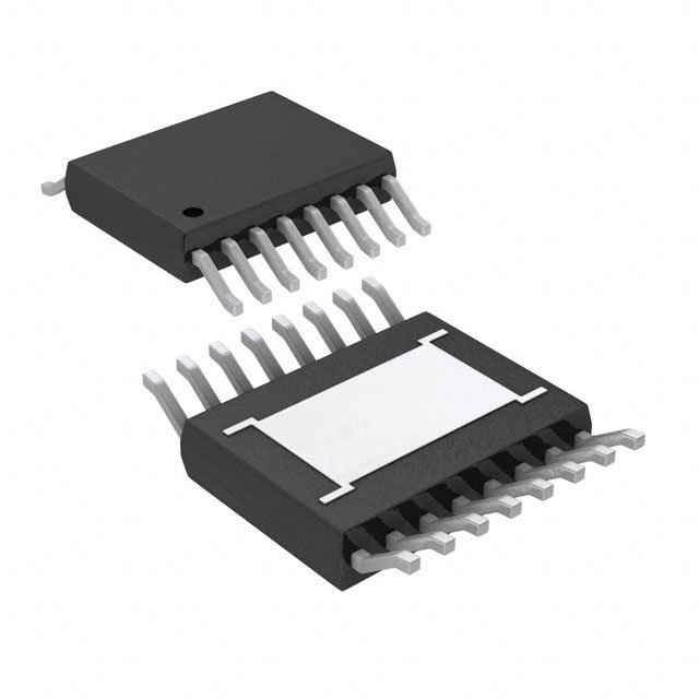
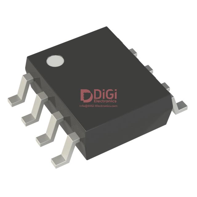
The LED2000DR integrates into design workflows via two primary package formats: the 8-lead Small Outline IC (SO8) and the Very Thin Fine Quad Flat Package No-lead (VFQFPN, 4 x 4 mm). The SO8 package delivers a compact form factor with solid mechanical robustness, balancing ease of handling during pick-and-place operations and broad compatibility with conventional PCB assembly processes. It provides reliable solder joint integrity across both leaded and lead-free processes, facilitating straightforward process qualification. The pin configuration and pitch follow industry conventions, minimizing risk during socket or pad layout stages. From a thermal standpoint, the SO8 offers adequate power dissipation for moderate current scenarios, with the molded body providing a predictable thermal resistance path conducive to repeatable performance during qualification testing.
The VFQFPN package advances the conversation by targeting designs where PCB real estate is at a premium and where heat management is critical. Its reduced z-height and X-Y footprint enable tight component clustering, directly benefiting advanced LED drivers deployed in high-density or portable applications. The exposed thermal pad on the underside is central to optimized heat evacuation: when coupled with properly dimensioned thermal vias beneath the package, junction-to-board and board-to-ambient thermal resistances can be minimized, supporting higher continuous load currents and reduced temperature drift in precision applications. This feature is particularly advantageous in automotive or architectural lighting modules where stringent luminaire efficiency must be balanced with form factor constraints.
Both package options comply with STMicroelectronics’ ECOPACK standards, ensuring alignment with global environmental directives. The integration of halogen-free molding compounds and materials validates these packages for applications with elevated ecological or regulatory requirements. The design facilitates seamless transition across international product certifications, de-risking large-batch manufacturing runs and aligning well with supply chains demanding RoHS and REACH conformity.
In practice, referencing official mechanical drawings—and analyzing the recommended land pattern and tolerance stack-up—proves crucial for first-pass PCB layout accuracy and solder joint reliability. Tolerance margins, along with coplanarity specifications, directly impact reflow process windows and yield. For the VFQFPN, special attention to solder paste stencil design and reflow temperature profiles further enhances void minimization beneath the thermal pad, ensuring consistent heat sinking into the PCB copper plane.
Application success often stems from matching package choice to system priorities. Designs emphasizing rapid assembly, straightforward inspection, and field-serviceability consistently leverage SO8. Use-cases demanding the tightest thermal margins and minimal PCB footprint, such as multi-channel backlighting or drone strobes, extract maximal benefit from VFQFPN’s exposed pad and minimized lead inductance. The package selection thus becomes an engineering tradeoff, balancing assembly risk, thermal design, and long-term reliability within the system’s operational envelope.
Potential equivalent/replacement models for LED2000DR
When seeking equivalent or replacement models for the LED2000DR, a detailed comparative analysis is essential to ensure seamless integration into existing systems. The foundational requirement is a step-down (buck) converter topology featuring fixed high-frequency switching. This architecture directly influences transient response, solution size, and EMI characteristics. A fixed switching frequency—typically in the hundreds of kHz to several MHz—facilitates compact magnetics and predictable behavior in noise-sensitive environments.
Synchronous rectification remains a core attribute for maximizing power conversion efficiency, particularly at higher current levels. By replacing the Schottky diode with a low-side MOSFET, conduction losses decrease, which is crucial in thermally constrained designs or where regulatory efficiency thresholds must be met. Adjustable current regulation, normally implemented via an external sense resistor, provides the necessary flexibility for tailoring LED drive levels. This design also enables closed-loop feedback, which enhances operational stability across component tolerances and environmental shifts.
Integrated protection features form the backbone of robust power delivery. Overtemperature, overcurrent, and output short-circuit protection are vital for system reliability and compliance with safety standards. Effective protection schemes reduce field failures and facilitate certification for safety-critical applications.
Dimming capabilities, specifically through PWM (pulse-width modulation) control, are a direct requirement for lighting systems demanding dynamic brightness adjustment. Support for both linear and PWM dimming widens the feasible target applications, from architectural lighting to automotive systems.
In evaluating alternatives—such as Texas Instruments LM3406 series, Analog Devices LT3474, or ON Semiconductor’s NCL30000 family—a thorough examination of each device’s electrical and functional implementation is required. The LM3406 series offers both analog and PWM dimming options and integrates similar protection blocks, making it a generally compatible selection for moderate current applications. The LT3474’s programmable output current and higher current range extend its suitability but introduce layout and thermal management considerations at the upper end of its range. The NCL30000 family differentiates itself with a wide input voltage rail, suitable for systems transitioning between supply domains. However, subtle differences in protection handling or dimming circuitry integration may necessitate firmware or PCB adjustments.
Switching frequency discrepancies between candidate components merit close scrutiny. The interaction between switching frequency, passive selection, and system EMI profile can result in measurable differences in efficiency and compliance. Thermal performance also varies; devices with marginally higher Rds(on) or suboptimal thermal pads may exhibit hotspots under identical load conditions, requiring careful thermal modeling and possibly the adaptation of heat sinking strategies.
Another practical aspect is package availability and pin compatibility. While datasheet functional parity is important, minor differences in pinout or package size often dictate the true ease of substitution, especially when updating legacy designs or leveraging existing PCB layouts. For design teams working within strict production timelines, minimizing PCB rework and verification cycles is a major consideration.
The nuanced selection process often reveals that no substitute is universally drop-in compatible across all key metrics; careful prototyping and validation in the end-application are instrumental in identifying subtle deviations. In real-world deployments, attention to loop compensation, dimming response time, and fault recovery behavior can distinguish a nominally compatible part from one that delivers true system-level robustness.
An integrated approach combining electrical analysis, thermal modeling, and application-level testing generally yields the best outcome. Leveraging deep familiarity with protection implementation—beyond listed datasheet features—can expose long-term reliability distinctions. The optimal replacement does not simply match functional checkboxes but aligns with the thermal, electrical, and system integration constraints unique to each end application.
Conclusion
The STMicroelectronics LED2000DR distinguishes itself through its blend of high integration and adaptability in power-efficient LED driving scenarios. At its core, the device leverages synchronous step-down topology, featuring a constant current regulation that minimizes flicker and enhances brightness accuracy even under wide input voltage variations. Circuit efficiency is fundamentally anchored in the careful selection of inductor and output capacitor ratings, where the designer must match electrical parameters—such as ripple current and ESR—to the LED array’s thermal and optical constraints. Precision in choosing low-ESR capacitors reduces output noise, supporting stable illumination, while the inductor must ensure low core losses at operational frequencies to prevent thermal hotspots and sustain long-term reliability.
Thermal management is paramount, particularly as power density increases in compact lighting modules. Effective layout strategies prioritize short and wide traces for current paths, coupled with generous copper pours beneath the device’s exposed pad to facilitate heat dispersion. The LED2000DR’s thermal shutdown features act as safeguards; however, practical experience confirms that proactive design reduces derating risks during high ambient conditions. Integrated overcurrent and overvoltage protection circuits bolster the robustness of end products, yet real-world deployments benefit from external TVS diodes and fast-blow fuses for peripheral fault containment.
Dimming capabilities, controlled via the device’s analog or PWM input, demand careful loop compensation to eliminate transient overshoot. Engineers focus on configuring the compensation network around the error amplifier to achieve a balance between dynamic response and stability across the LED operating range. In precision applications—such as architectural accent lighting or automotive signal lamps—test results validate that fine-tuned compensation not only stabilizes brightness but also suppresses audible noise linked to inductor magnetics under rapid modulation.
Application-specific nuances further inform component selection and layout choices. Automotive designs impose stringent EMI requirements; a shielded inductor and synchronized input filtering with X/Y capacitors consistently yield compliance during conducted and radiated emission testing. In outdoor signage, moisture and dust ingress necessitate conformal coating for both the LED2000DR and adjacent passive devices. Experience reveals that regular thermal cycling and vibration screening can preemptively address latent reliability threats, setting benchmarks for maintenance-free operation over extended service lifetimes.
When benchmarking alternatives, scrutiny should extend beyond headline efficiencies and max output figures. The LED2000DR’s pinout flexibility and compact SO-8 exposed pad package streamline PCB design without constraining routing for dual-channel or color-mixing architectures. Compatibility with a wide spectrum of LED voltages and currents expands design latitude, reducing SKU fragmentation and simplifying supply chain logistics. Ultimately, holistic evaluation accounting for protection schemes, dimming finesse, thermal resilience, and application-specific reliability standards enables confident deployment in demanding lighting installations. Practitioners who iterate their designs—including empirical validation cycles—gain insights that optimize not merely performance metrics but also manufacturability and operational endurance, solidifying the device’s role in next-generation lighting infrastructure.