>
>


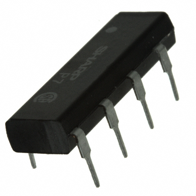
Product overview: Sharp S202S02F solid state relay
The Sharp S202S02F solid state relay (SSR) leverages optoelectronic coupling to provide robust AC load switching in environments demanding both high reliability and electrical isolation. Its SPST-NO Triac output configuration is optimized for control scenarios where discrete on-off switching of up to 8A RMS AC loads via logic-level DC inputs is required. A key mechanism is the integration of infrared-emitting diodes and phototriac detectors, positioned to minimize signal cross-talk and reinforce galvanic isolation, typically rated around 5000 Vrms. This architectural choice mitigates the risk of voltage transients from load-side disturbances propagating toward sensitive control electronics, a critical consideration in industrial automation deployments.
The S202S02F’s four-pin SIP through-hole package streamlines PCB layout and thermal management, enabling dense array configuration and straightforward fault replacement in maintenance cycles. When designing temperature-critical systems, empirical observations show the relay's footprint and low thermal resistance foster stable operation under continuous load, supporting application in HVAC, switched lighting, and motor control subsystems. Engineers often exploit the fast response time and absence of mechanical contacts to achieve silent switching, reduced EMI, and longer operational lifespan compared with traditional electromechanical relays, especially in repetitive actuation use cases.
Phototriac-triggered SSRs, such as the S202S02F, inherently suppress back EMF and electrical arcing by virtue of their bidirectional current control, which supports alternating phase switching and enhances system durability. Practical circuit integration typically pairs the relay with zero-cross detection logic, optimizing turn-on at minimum AC voltage differential and thereby attenuating surge currents. This technique extends relay service life and contributes to regulatory compliance related to electromagnetic compatibility (EMC), a non-trivial concern in mixed-voltage assembly lines or distributed control networks.
In application, balancing isolation voltage, surge susceptibility, and load characteristics drives selection of SSR components. Intensive field use underscores the importance of precision input characteristics; the S202S02F’s LED input is compatible with TTL and CMOS logic standards, simplifying design for controllers or microprocessor interfaces. Its operational profile suits not only large-scale automation but also laboratory-grade switching, where deterministic operation and minimal propagation delay are paramount.
A notable advantage lies in system resilience: deployment of SSRs such as the S202S02F inherently reduces maintenance overhead and facilitates modular upgrade paths due to their non-mechanical nature. This translates directly to enhanced uptime and lower lifecycle costs, distinguishing solid-state solutions as future-ready in dynamic electrical environments.
Key specifications and operating parameters of the Sharp S202S02F
The S202S02F demonstrates a robust combination of electrical and safety parameters suitable for isolating medium-power AC loads. At its core, optically isolated solid-state switching enables high-speed control devoid of mechanical arcing, thereby reducing maintenance needs while enhancing reliability in densely packed assemblies. The device’s capacity to deliver up to 8A RMS at voltages spanning from 80V to 240V AC allows seamless integration into circuit designs where moderate load switching must maintain predictable performance regardless of supply voltage fluctuations.
Precise input characteristics optimize interfacing flexibility. A typical forward voltage drop of 1.2V at 20mA, coupled with a minimum trigger current threshold of 8mA, ensures compatibility with microcontroller outputs and digital signal lines commonly encountered in remote switching or automation applications. Input drive requirements remain manageable even under fast cycling sequences, promoting consistent trigger response while reducing excess power dissipation on logic boards.
The zero crossing detector embedded within the device’s control circuit achieves low-noise switching and substantial mitigation of electrical transients. With a maximum zero cross voltage threshold of 35V, the device activates only near the AC sine wave’s crossover point, which limits electromagnetic interference and sudden inrush currents to surrounding equipment. This capability becomes critical when deploying the S202S02F in lighting control, motor actuation, or sensitive instrumentation panels, where clean transitions directly impact overall system longevity and user experience.
Output-side resilience is engineered through a repetitive peak off-state voltage rating of 600V and a surge tolerance reaching 80A for brief durations. These ratings provide robust protection against voltage spikes and irregular loads, making the module suitable for industrial applications exposed to unpredictable power networks or frequent switching events. Experience shows that selecting components with high surge tolerance and generous voltage margins significantly improves uptime and reduces premature failure rates in demanding operational schemes, particularly within relay panels and distributed control units.
Thermal stability further strengthens the operating envelope. The device reliably functions across a wide temperature band from -25°C to +100°C, with its storage specification extending down to -30°C and up to +125°C. Such parameters allow mounting near heat-generating components without distortion of performance metrics, facilitating dense PCB layouts or enclosure installations where ambient temperature can vary widely due to process activity or external environment.
Isolation integrity is underscored by a 4.0kV rating between input and output stages, satisfying stringent safety benchmarks in mixed-voltage systems. This high isolation value promotes secure interaction between low-voltage control boards and mains-level power sections. Integrated optical isolation, supported by rigorous insulation materials, minimizes risk in field installations and in modular assemblies where inter-system voltage differentials frequently arise.
A careful examination of these technical layers reveals that the S202S02F is not only a versatile solid-state relay but also a proven solution for noise-sensitive, harsh-load scenarios. Prior deployment in control frameworks highlights its practical strengths: trouble-free AC load switching, resilience during short spikes, and straightforward design-in for automation circuits. Optimal usage results from balancing inverter drive characteristics, thermal design considerations, and noise management principles, all underpinned by consistent safety margins and long-term reliability. This holistic approach, coupled with attention to device ratings and system context, ensures engineers achieve durable performance while retaining operational flexibility.
Internal structure and functional features of the Sharp S202S02F
The Sharp S202S02F integrates fundamental optoelectronic and solid-state switching technologies within a compact SIP 4-pin package. At its core, an infrared-emitting diode (IRED) serves as the input transducer, converting control signals into optical energy. This light is captured by a monolithic phototriac detector, which precisely actuates a main output triac responsible for handling AC loads. This optically isolated architecture provides a dielectric barrier between the input and output stages, efficiently mitigating risk of high-voltage surges coupling back into control logic, a necessity when bridging microcontroller-level signals with appliance or industrial mains.
One of the device’s defining functional features is its built-in zero crossing detector. This circuitry monitors the phase of the incoming AC waveform, enabling activation of the output triac only when the AC voltage transitions through zero. Such synchronization minimizes transient electromagnetic emissions and voltage spikes that typically accompany forced switching at arbitrary voltage levels. The result is both improved system electromagnetic compatibility (EMC) and reduced mechanical and thermal stress on the load, extending both relay and end-device lifetime in real-world deployment.
The mechanical PIN footprint adheres to standardized SIP layouts, ensuring drop-in suitability for PCB-based systems and supporting high-density component placement. Inputs are dedicated for logic-side activation, while outputs (Triac T1 and T2) interface directly with the AC load circuit. Lead finishing options without hazardous substances reflect compliance with RoHS and broader sustainable design practices—an increasingly significant selection criterion for contemporary hardware engineers.
In practical circuit environments, the S202S02F demonstrates resilience in noisy operating conditions, maintaining reliable turn-on even under variable control signal quality due to the noise-immunity inherent in optoisolation. For example, during inductive load switching, zero crossing detection not only protects sensitive driver electronics but also downregulates surge currents that could induce nuisance tripping in upstream protection devices or degrade connected load performance over thermal cycles.
A nuanced engineering consideration emerges in pairing the relay correctly with load characteristics and drive circuitry. Overdriving the input or mismatching thermal dissipation capacity can undermine long-term reliability. Careful attention to recommended forward current, load phase angle, and PCB trace layout for heat removal is therefore vital to maximize operational stability and device lifespan.
Combined, the device’s internal structure and advanced signal conditioning enable robust interfacing capabilities between low-voltage digital systems and high-voltage power domains. This architecture reflects a pragmatic convergence of compact packaging, functional safety, and application-layer utility—central for smart appliances, industrial control, and power management platforms where noise resilience and longevity are prioritized.
Thermal management and mounting considerations for the Sharp S202S02F
Effective thermal management is foundational for the reliable performance of the Sharp S202S02F solid-state relay, especially as output currents approach the upper specification limits. The key thermal challenge arises from the direct link between power dissipation, load current, and both ambient and case temperatures. Thermal derating curves provided by the manufacturer visually quantify the safe operating area, revealing how increased current draw elevates device temperature and narrows the permissible operating envelope. Recognizing this relation is essential for avoiding excessive junction temperatures and for preserving long-term device integrity.
The mounting configuration exerts a critical influence on heat dissipation efficiency. To achieve optimal thermal conduction away from the relay, the selection and preparation of heat sinks must be executed with engineering precision. Aluminum plates, defined by both surface area and thickness, serve as the preferred medium; their dimensions should be in line with the power figures observed in the intended operational scenario. The interface between the relay and heat sink greatly impacts thermal resistance—application of a uniform, thin film of high-conductivity thermal grease is necessary to promote intimate metal-to-metal contact and to eliminate microscopic air gaps, which otherwise act as thermal insulators. In scenarios where electrical isolation is mandated by circuit topology or safety requirements, the insertion of a compliant insulation sheet is recommended. Selection of this barrier material warrants attention to both electrical and thermal conductivity parameters, as suboptimal choices can inadvertently increase junction temperature.
Mechanical attachment protocols also demand strict adherence. The recommended tightening torque range of 0.3–0.5 N·m for M3 screws is a result of careful balance: ensuring robust physical connectivity without generating mechanical stress fissures in the relay’s body or causing thread stripping. This becomes particularly relevant in high-vibration environments or where uneven mounting surfaces could introduce warping forces. Consistent torque application can usually be streamlined through the use of calibrated torque drivers, substantially reducing risk during assembly in batch production.
Heat sink orientation impacts its convection performance. Aligning the mounting plate vertically, rather than horizontally, exploits natural convection: heat rises, drawing cooler air over the heat sink’s surface most efficiently in this positional configuration. This design practice is especially consequential in enclosures with passive airflow or where forced ventilation is impractical due to noise, size, or energy constraints. In field deployments, observations consistently reinforce that units with correct vertical heatsink orientation demonstrate notably lower operational temperatures and fewer thermal-induced deratings, underscoring the importance of physical layout during cabinet or enclosure planning.
Applying these principles translates into the S202S02F maintaining its rated 8A load capacity even amid fluctuating ambient conditions or extended duty cycles. Failure to strictly manage thermal and mounting parameters is a primary root cause of unexpected relay shutdowns and diminished service life. Robust installation procedures and disciplined thermal interface practice, coupled with proper heat sink selection, constitute an actionable engineering path to reliable, long-term SSR utilization in demanding power switching applications. Critical evaluation of installation specifics at the design stage, along with consideration of case-by-case environmental factors, ultimately empowers high-density, low-failure system architectures.
Application scenarios and engineering design considerations for the Sharp S202S02F
Application scenarios for the Sharp S202S02F center on systems that require galvanic isolation and reliable SSR control bridging high-voltage AC circuits and sensitive low-voltage logic outputs. This optically isolated TRIAC-output SSR is particularly suited to microcontroller-based automation tasks, where direct triggering of line-level loads—such as motorized dampers, relay banks, industrial fan arrays, and heating or lighting channels—demands both electrical isolation and immunity to low-level control noise. The integrated zero-cross detection topology mitigates high inrush current events and minimizes electromagnetic interference during turn-on by ensuring load activation aligns with the AC mains voltage's zero crossing point. This feature translates into lower acoustic and electrical noise, smoother load engagement, and extended operational longevity in resistive or low-inductance environments.
The device architecture is optimal for switching resistive loads such as filament lamps, heaters, and simple solenoids, where current and voltage waveforms remain in phase. However, the device’s switching mechanism is sensitive to line disturbances common in industrial and commercial facilities—specifically, voltage transients with sharp dV/dt characteristics. Inductive components, like shaded-pole motors, solenoid-operated actuators, or transformer primaries, present a risk of false triggering or misfire due to the rapid voltage shifts they introduce. Effective circuit ruggedness hinges on incorporating RC snubber networks tailored to the specific application's worst-case switching profile. Empirically, closest proximity layout of a 0.022 µF capacitor in series with a 47 Ω resistor across output terminals often curtails false triggers and suppresses high-frequency ring-back propagation. Adjustments above these baseline values can be informed by iterative bench testing, observing turn-on jitter, and waveform integrity under genuine load. Continuous operation experience indicates that optimal snubber tuning reduces service callouts and eliminates erratic switching even in noise-prone machinery bays.
Enhancing AC switching resilience further, deploying varistors across the SSR output terminals intercepts overvoltage spikes, further suppressing surges that typify industrial brownouts or system restarts. Placement choice and absorption rating require review against facility-specific transients—particularly in lightly conditioned grids or installations sharing supply with heavy switching devices. These layered protection measures directly bolster the long-term field reliability of control panels based on S202S02F-outfitted layouts.
Selecting between zero-crossing and non-zero-crossing variants is not merely a matter of load type but of dynamic coordination between control waveforms and the SSR's intrinsic response. In load environments with significant phase lag—such as high-torque motors or systems with non-linear loads—a zero-crossing version may introduce commutation issues, resulting in incomplete or late switching. In these contexts, a non-zero-cross alternative like the S202S01 is recommended, granting asynchronous control independent of the AC mains’ crossing instances. Experience shows that in mixed-load installations, a hybrid deployment of SSR types, appropriately mapped to load behavior, delivers optimal system integrity. A disciplined approach to SSR selection, considering both load physics and control-loop requirements, is fundamental in building robust, scalable power interfaces within complex automation ecosystems.
Regulatory compliance and environmental ratings of the Sharp S202S02F
Sharp S202S02F’s adherence to regulatory and environmental benchmarks reflects purpose-driven engineering for industrial reliability and global deployment. It acquires UL508 and CSA 22.2 No.14 certifications, achieved only through meeting strict requirements for control circuitry and mechanical endurance. Such certifications are not generic—they indicate the relay’s suitability for integration within safety-centric machinery, automated manufacturing lines, and process instrumentation, where liability and operational continuity depend on devices maintaining electrical insulation, arc resistance, and fail-safe switch characteristics under variable loads.
Technical confidence in harsh or code-regulated settings stems from the component's enclosure resin attaining a UL94V-0 flammability rating. This quantifies ignition-resistance and rapid self-extinguishing properties—a critical metric in control panels, HVAC assemblies, or transportation controls that must demonstrate compliance with high fire safety codes. Preservation of circuit integrity during potential thermal events originates at the polymer chemistry level, translating to fewer field failures in densely packed enclosures or unconditioned spaces.
The MSL 1 moisture sensitivity ensures logistical and operational advantages. With unrestricted ambient exposure during SMT assembly or maintenance, this relay eliminates the requirement for controlled storage or dry-room handling, reducing both process complexity and the probability of solderability defects associated with absorbed moisture. This facilitates streamlined inventory management and enables just-in-time manufacturing processes, with mitigated risk for latent damage that can compromise insulation resistance or relay actuation.
Classification as EAR99 under U.S. export controls implies the absence of application-specific restrictions, streamlining cross-border procurement for OEMs serving telecommunications, data centers, energy distribution, and OEM user bases spanning diverse regulatory environments.
In practice, these specifications enable confidence in deploying the S202S02F where safety validation and regulatory harmonization are primary constraints. Designs benefit from its multilayered compliance, with real-world implementation highlighting less friction in both product qualification phases and downstream support. This device, in effect, becomes an enabler for rapid product rollouts across multiple jurisdictions—subtle optimizations in material choice and certification strategy yielding tangible reductions in time-to-market and post-installation risk.
A strategic insight is that the synergy between compliance and environmental robustness, when embedded deeply at the component level, provides a foundation for scalable, low-risk system architectures. Engineering decisions made during early relay selection—distilled from such regulatory clarity—can unlock both operational flexibility and long-term cost efficiency in mission-critical applications.
Potential equivalent/replacement models for the Sharp S202S02F
When addressing the obsolescence of the Sharp S202S02F solid state relay (SSR), it is essential to systematically evaluate functional equivalents that align with both technical requirements and supply chain continuity. Within Sharp’s SSR lineup, the S202S02 emerges as the most direct replacement, featuring the same output parameters: a 600V peak off-state voltage and an 8A RMS on-state current. The primary distinction lies in its lead solder plating, which must be cross-checked against RoHS and environmental standards for specific application deployments. Selection hinges not only on identical electrical ratings but also on PCB layout compatibility and heat dissipation conditions, both critical in densely populated assemblies or in retrofitting legacy boards.
For systems where zero crossing detection is nonessential—such as applications demanding rapid random turn-on or tighter timing control—the S202S01 or S102S01 variants deliver a functionally alternative solution. These models preserve current handling capabilities and maintain the same mounting topology. The absence of zero-cross circuitry modulates their switching dynamics; reduced turn-on delay improves performance in responsive load control, but may require recalibration of EMI mitigation strategies within sensitive AC line environments. Such trade-offs underscore the necessity for thorough signal integrity verification during design qualification.
Operational scenarios occasionally present the option to select the lower-rated S102S02F, offering 400V peak off-state tolerance. Deployment here is only justified when the system’s AC input is constrained well below this threshold, ensuring adequate design margin and long-term reliability. In practice, derating strategies become essential, particularly under variable line conditions or in geographies with unstable power infrastructure. Standard engineering practice dictates that device voltage ratings should consistently exceed the highest anticipated line surge to avert premature device failure or nuisance tripping.
In all replacement considerations, attention must pivot to real-time sourcing data and ongoing manufacturer communications. Product discontinuations propagate through supply chains in unpredictable patterns, impacting component lifecycles and after-market availability. Qualification workflows benefit from establishing second-source policies or preemptive validation of form-fit-function compatible products from other suppliers—especially for high-volume production runs or critical maintenance scenarios. Experience highlights the risk of latent incompatibilities arising from subtle physical or electrical variances, reinforcing the value of rigorous cross-qualification and extended temperature/humidity testing before mass implementation.
Ultimately, homologation of SSR substitutes must be approached as a multidimensional process. Beyond raw electrical specifications, integration success depends on comprehensive mechanical, regulatory, and logistical assessment, highlighting the interplay between intrinsic device features and their contextual system roles. This layered evaluation not only preserves system integrity but also futureproofs against downstream procurement disruptions, a recurring pattern in long-lifecycle industrial and consumer designs.
Conclusion
The Sharp S202S02F solid state relay integrates advanced semiconductor switching with optically isolated control, fulfilling stringent requirements in high-reliability AC load management scenarios. At the core of its design, the device leverages zero-crossing detection to suppress electrical noise and minimize stress on both the relay and connected circuitry, a key advantage in environments prone to transients or where the longevity of components is critical. Its isolation voltage ratings, realized through encapsulated construction and optimized optocoupler layouts, ensure secure segregation between input and output—vital for complex automation and signal interfacing approaches where cross-domain interference must be managed precisely.
Practical deployment often centers around its 8A, 240V AC rating, allowing direct replacement of legacy electromechanical relays within existing systems while conferring the benefits of silent operation, reduced mechanical wear, and extended service intervals. The footprint adheres to established SSR standards, facilitating plug-in compatibility across standardized industrial control panels and modular expansion frameworks. Engineers embedding the S202S02F in distributed load architectures record measurable gains in response consistency and EMI suppression, especially in applications such as motor starters, lamp banks, or HVAC actuators regulated by PLCs.
Thermal management emerges as a pivotal aspect of robust SSR integration. Real-world load cycling introduces dynamic heating effects; designers employ dedicated heat sinks or forced air solutions, calculate derating under peak ambient conditions, and ensure clearance around the relay for passive cooling. Selection of proper PCB traces, orientation, and enclosure material directly affects the relays' operating envelope, so thorough upfront simulation and empirical validation feature prominently in successful deployments. Countermeasures against inrush currents and harmonics, achieved through careful load profiling and sometimes the addition of snubber circuits, further safeguard both relay and load, especially in inductive or capacitive switching contexts.
Regulatory compliance, from UL to IEC, underpins acceptance in diversified international markets. Pre-certification of the S202S02F simplifies approval for finished assemblies and expedites product timelines, especially where rigorous electrical isolation and fire safety ratings present bottlenecks in global expansion. Experienced practitioners routinely cross-examine datasheets against application-specific requirements—evaluating parameters such as turn-on/turn-off times, leakage currents at elevated temperatures, and resistance against surge events. Interchangeability with equivalent SSR models from both Sharp and other vendors affords flexibility in sourcing, lifecycle management, and scalability, essential in contemporary automation and process control settings faced with varied supply chain challenges.
Underlying the technical attributes, a strategic insight emerges: the S202S02F exemplifies a rational balance between innovation and field-proven reliability. Its integration platform empowers the design of high-uptime, low-maintenance systems while affording the latitude for incremental upgrades and standardization across geographically distributed installations. By aligning SSR choice with the granular operational realities—load characteristics, environmental stressors, certification regimes—the deployment outcome reliably advances overall system robustness and longevity.