 >
>


Product overview: VIPER12ASTR-E STMicroelectronics IC offline switch
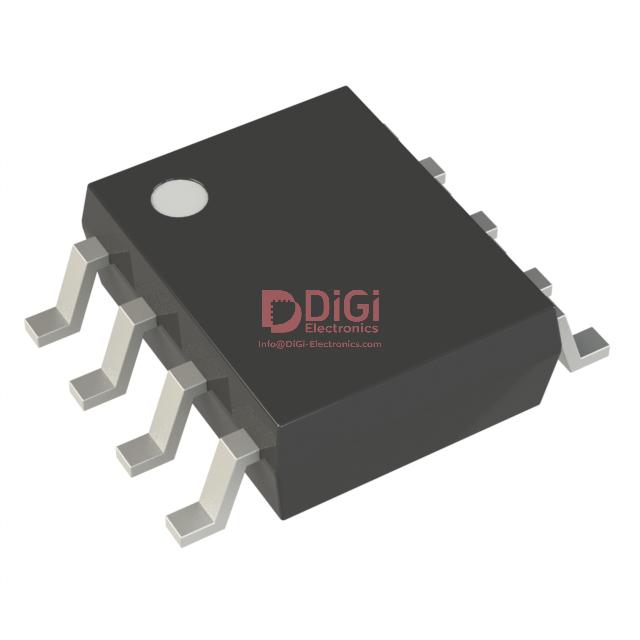
The VIPER12ASTR-E from STMicroelectronics exemplifies the convergence of integrated power management and advanced control logic, specifically tailored for low-power offline switched-mode power supplies. Embedding a current-mode PWM controller with a high-voltage power MOSFET within a compact 8-pin SOIC footprint, the device achieves significant reductions in external component count, PCB area, and assembly complexity. This monolithic integration not only simplifies thermal management and EMI containment but also facilitates rapid design iterations in constrained environments where reliability and efficiency are non-negotiable.
Central to the VIPER12ASTR-E’s architecture is its primary-side regulation capability, which removes the dependency on secondary feedback loops and optocouplers. By leveraging integrated error amplifiers and reference circuits, the device maintains tight output regulation across a wide input voltage range, optimizing both standby and active mode efficiency. The device’s inherent high-voltage startup circuitry enables direct connection to rectified mains, eliminating auxiliary startup resistors and accelerating response times during line transients and brown-in conditions.
A distinctive feature of the VIPER12ASTR-E is its robust suite of protection schemes—overload, open-loop, and thermal shutdown protections are built-in, ensuring operational resilience in both consumer-facing products and industrial automation subsystems. These protections act seamlessly without external intervention and contribute directly to elevated MTBF figures, particularly in mission-critical, always-on applications like auxiliary power for motor drives and home appliance logic supplies.
When developing compact battery charger adapters or standby power supplies for displays, the reduction in bill-of-materials and board footprint directly translates into faster time-to-market and lower overall system costs. Field experience highlights that the tightly-integrated power stage substantially mitigates layout-induced vulnerabilities, leading to improved EMI compliance results and predictable startup behavior across wide input surges, a recurring challenge in grid-unstable regions.
As power architectures increasingly prioritize standby efficiency and global regulatory compliance, the VIPER12ASTR-E’s integrated burst-mode operation achieves sub-30mW no-load power without auxiliary housekeeping or control ICs. This is fundamental for meeting evolving eco-design standards, particularly in smart home nodes and networked sensor modules, where idle-time energy use must be minimized.
The system-level impact is evident in reduced design cycles, enhanced reliability, and scalable manufacturing—attributes that reinforce the value proposition for engineers working within space, cost, or time-constrained product platforms. The VIPER12ASTR-E exemplifies how high integration, comprehensive protection, and primary-side control can transform the development and deployment of low-power offline SMPS designs, pushing the boundaries of miniaturization and efficiency across diverse market segments.
Core electrical and functional characteristics of the VIPER12ASTR-E
The VIPER12ASTR-E integrates a fixed 60 kHz current-mode PWM controller, establishing stable frequency operation that streamlines EMI compliance while enabling tight regulation of output voltage and current. The inherent current-mode topology offers two major technical benefits: inherent cycle-by-cycle current limiting that enhances fault tolerance, and superior load transient response due to immediate feedback on current changes. These features directly translate to improved regulation under dynamic conditions, such as sudden load steps common in power supplies for embedded and industrial control systems.
Operating across an extended $V_{DD}$ range of 9 V to 38 V, the device adapts efficiently to diverse primary-side auxiliary supply designs. This wide operating window facilitates universal power supply development, especially where input voltage fluctuations or brownout scenarios are probable. The high-voltage start-up current source further minimizes BOM complexity; by eliminating the need for additional discrete components for start-up biasing, designers achieve simpler PCBs and enhanced reliability. In practical circuit assemblies, this characteristic noticeably reduces layout constraints in low-cost, space-restricted applications, from IoT node adaptors to industrial sensors.
The chip’s protection suite encompasses overtemperature shutdown, overcurrent protection (OCP), and overvoltage shutoff with auto-restart. Each protection event triggers an internal reset sequence rather than a latched fault, ensuring automatic recovery post-fault and minimizing maintenance cycles. In the field, such features deliver high availability in end-use systems including isolated auxiliary power for white goods, smart meters, and building automation modules. The aggressive thermal protection thresholds, when coupled with fast recovery, prevent prolonged overstress periods while preserving operational continuity. Additionally, experienced engineers often leverage these protections as fail-safe design anchors, intentionally sizing external components to trip faults visibly during validation for robust corner-case coverage.
From an electrical rating perspective, the VIPER12ASTR-E delivers up to 8 W in SO-8 and 13 W in DIP-8 at European nominal mains (195–265 VAC), while supporting 5 W and 8 W respectively under the broader 85–265 VAC input specification. This rating model enables precise device selection relative to application derating requirements and environmental constraints. Power limitation mechanisms are tightly controlled by the internal PWM and current-limit loops, supporting stable continuous conduction even with capacitive loads typical in offline AC-DC convertors.
Low standby power is achieved through an intelligent automatic burst-mode operation, significantly reducing switching losses during light-load or standby states. This is especially advantageous for compliance with modern efficiency standards—such as ErP Lot 6 and DoE Level VI—where power adapters and appliances must demonstrate sub-100 mW standby draw. In implementation, careful PCB parametric tuning, particularly of feedback compensation networks and primary bias resistors, yields repeatably low standby currents.
Thermal behavior is shaped by power package selection and PCB layout. The optimized SO-8 and DIP-8 footprints are intended for standard FR4 substrates, with manufacturer-specified copper pours under the package to spread and conduct heat away efficiently. In extensive production use, simulation-driven placement of thermal vias, as well as adherence to recommended copper footprint areas, has shown to deliver junction temperature headroom even at maximum rated loads and under extended line voltages. Such detail not only ensures electronic reliability but also preserves margin for operation in thermally challenged or unventilated enclosures—a frequent requirement in harsh industrial or outdoor environments.
A distinguishing insight with the VIPER12ASTR-E lies in its interplay between simplicity and robustness. Integration of critical front-end and protection features reduces the opportunity for field failures related to external part count and makes the platform especially well-suited to mass-market power supplies where efficiency, safety, and cost must be simultaneously balanced. The component’s architectural balance serves as a highly adaptable building block for modern AC-DC solutions demanding compactness without compromising on lifetime or safety mandates.
Application scenarios and power delivery capabilities of VIPER12ASTR-E
The VIPER12ASTR-E integrates a high-voltage startup circuit, PWM controller, and MOSFET power switch into a compact package, targeting offline switch mode power supplies that require high efficiency, reduced bill-of-materials, and minimal design complexity. Its architecture supports flyback, non-isolated, and isolated topologies, leveraging quasi-resonant or fixed-frequency operation. The unified primary-side control with an embedded startup circuit streamlines the system and enhances performance in low-power converters.
In battery charger applications, the IC’s precise switching control facilitates rigorous implementation of nonlinear charging profiles, critical in lithium-ion battery charging. Its capability to maintain reliable operation down to sub-volt output levels allows seamless transition between constant current and constant voltage regions. This addresses a significant engineering challenge—delivering tightly regulated output even during deep battery discharge or at the knee of the charging curve, ensuring safety and battery longevity. Designers routinely exploit the device’s robust secondary-side regulation support, using optocouplers and TL431 references to guarantee tight output tolerance and fast transient response. Practical deployments confirm that loop stability and EMI performance are simplified, with significant reductions in transformer size and cost owing to the controlled switching stress and low standby consumption.
When integrated into standby power modules for consumer electronics, the VIPER12ASTR-E enables compliance with global energy efficiency mandates, such as stringent no-load and standby power requirements. The integrated protection features—overload, over-temperature, and short-circuit—bring further resilience in deployment, particularly in scenarios where field failures must be minimized. The IC’s jittered switching frequency and fixed peak current modulation contribute to low conducted and radiated emissions. These inherent features translate to reduced design iterations and faster agency certification for power supply modules in TVs and monitors, where layout constraints and thermal budgets are acute.
In the context of auxiliary power in industrial drives and automation equipment, reliability and predictable behavior under abnormal line or load conditions are paramount. The device's undervoltage lockout, brownout detection, and output short-circuit protection mechanisms support such requirements. System architects leverage the manageable thermal profile and rugged integrated power stage, resulting in supplies tolerant to harsh electrical environments. Field experience reveals the benefit of the device’s primary-side biasing options, which enable flexible startup sequencing and rapid recovery from power interruptions, crucial for process continuity in industrial automation cells.
A core insight is the device’s holistic approach—merging flexibility with robust integration. This convergence provides a tangible reduction in external component count, minimizes PCB footprint, and streamlines thermal and EMI management. The architecture of the VIPER12ASTR-E emphasizes fault tolerance, versatility, and efficiency, which pivots it from being a mere switcher IC to a strategic platform for modern, compact offline SMPS designs across battery-powered, standby, and auxiliary supply ecosystems.
In-depth analysis of VIPER12ASTR-E’s control architecture and operating principles
A detailed examination of the VIPER12ASTR-E’s control architecture reveals a layered integration of peak current-mode mechanisms, specifically tailored for applications demanding high efficiency and stringent regulation. Central to this design is the adoption of a peak current-mode control loop, which diverges from traditional voltage-mode designs by directly utilizing drain current sensing in conjunction with a current-driven feedback (FB) pin. Unlike voltage-feedback systems, the FB pin on this controller receives a defined current signal, establishing a direct, noise-immune path for loop compensation and response tuning. This enables precise realization of both voltage- and current-regulation, achieving the “rectangular U-I” output profiles often necessary in compact charger modules, USB power delivery, and adaptive supply units.
The internal architecture buses the sensed MOSFET drain current and external FB current through a resistor network, jointly referenced against a tightly regulated threshold voltage. When the sum reaches the trip point, the switching cycle is promptly terminated. This dual-sensing strategy delivers several operational advantages. First, feedback bandwidth and transient response are sharpened, as the current-mode feedback loop responds practically instantaneously to load or line perturbations. Second, inherent peak current limitation acts as a first line of defense against output faults and short circuits, often obviating the need for additional overcurrent protection components in downstream circuitry. Moreover, the current-mode approach simplifies loop compensation under varying output conditions—a critical benefit when designing for wide-output, fast charging scenarios or secondary-side current regulation.
Under light-load or standby conditions, the controller transitions into a tightly managed burst mode. Switching pulses are clustered in short bursts with intervening idle intervals, minimizing both core and switching losses. This mechanism directly targets modern requirements for sub-30mW no-load consumption and passes rigorous global standby directives without the complexity of auxiliary power rails or controllers. In practical design iterations, particular attention is paid to the selection and layout of the current sense resistor and feedback filtering, since noise or parasitic coupling can introduce jitter or false triggering in high dI/dt environments. Proper PCB routing—short, low-impedance feedback loops and segregated power-ground—is essential to extract the full benefit of the architecture.
Deploying the VIPER12ASTR-E in adaptive charging or auxiliary power supplies, system engineers can exploit its dual-mode regulation to ensure consistent output in the face of both variable load and input. For example, in smart charger applications, where a gradual transition from constant current to constant voltage is required, the device’s ability to interpret and merge the feedback signals in hardware streamlines design complexity and delivers predictably swift transition behavior. The decision to operate with current-mode regulation at the feedback interface also mitigates issues with optocoupler CTR drift or secondary-side regulation error, thus improving long-term system stability and reducing field failures.
An additional point of differentiation is the way this control method facilitates robust EMI performance. By leveraging a current input at the FB pin and avoiding high-impedance voltage-divider networks, susceptibility to common-mode disturbances is meaningfully reduced—a nontrivial requirement in environments with strict conducted emission limits. Thermal stress in power components is also alleviated due to rapid current limit enforcement and reduced overshoot, which directly translates to longer component lifetimes and improved system reliability.
The device’s architecture embodies a convergence of performance, efficiency, and system protection, uniquely positioning it for power-critical embedded applications where regulatory, thermal, and reliability demands converge. By prioritizing direct current-mode feedback and seamless burst operation, the VIPER12ASTR-E sets a strong benchmark for next-generation offline switcher controllers in both consumer and industrial designs.
Start-up and protection mechanisms in the VIPER12ASTR-E
Start-up sequencing within the VIPER12ASTR-E relies on a high-voltage, integrated startup current source engineered for rapid, reliable circuit activation. This element delivers controlled current to the $V_{DD}$ pin immediately after input voltage is applied, thereby charging the supply capacitor to the device’s turn-on threshold with precise timing. Such deterministic biasing ensures the controller exits undervoltage lockout conditions without delay, a critical factor for power supplies subject to frequent interruptions or demanding cold-start profiles. The inclusion of a dynamic disconnect mechanism—activated once the auxiliary winding generates sufficient bias—serves dual roles: preventing sustained leakage and elevating overall conversion efficiency by suppressing unnecessary dissipation during steady-state operation.
The device embeds a tiered protection strategy designed for autonomous fault handling and recovery. Overvoltage protection utilizes high-speed detection circuits tuned to reset post-transient, maintaining system uptime even under line surges. Thermal protection is fortified by real-time analog sensing, enabling prompt shutdown and automatic recovery cycles. This approach curtails the risk of silicon degradation and prevents irreversible faults due to excessive junction temperatures, especially in confined form factors lacking active cooling. Overcurrent limitations leverage tight integration with the feedback modulation loop, ensuring accurate discrimination between transient overloads and sustained faults. This level of granularity preserves system stability, mitigating the chance of nuisance tripping while safeguarding core components.
In practice, the device’s layered safety provisions streamline design-to-certification cycles for products destined for broad deployment. Engineers benefit from robust protection that complies with regulatory standards across fluctuating mains and variable environmental stressors. The seamless integration of startup and fault-handling circuits eliminates the need for external protection blocks, reducing BOM complexity while boosting long-term reliability. A notable insight is that the architecture’s inherent self-recovery and adaptive power management mechanisms subtly expand operational boundaries, permitting optimized headroom for aggressive thermal or transient specifications without sacrificing regulatory compliance. This enables designers to harmonize efficiency, ruggedness, and footprint constraints—a frequent challenge in contemporary switch-mode supply engineering.
Implementation considerations and package options for VIPER12ASTR-E
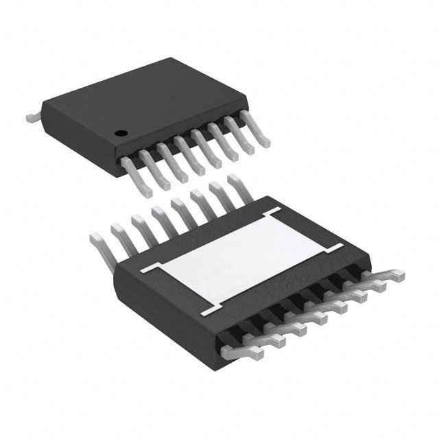
Integration of the VIPER12ASTR-E power IC into compact switched-mode supplies requires careful alignment of device characteristics with board-level design priorities. The SO-8 package format not only optimizes physical footprint, but—through pin pitch and isolation geometry—maintains sufficient creepage and clearance to meet established safety norms even in high-density layouts. For high-volume product platforms where space efficiency is critical, this feature supports aggressive PCB stacking or component clustering without sacrificing regulatory compliance.
The operating $V_{DD}$ envelope, spanning a wide input range, enables direct connection to auxiliary transformer windings, generating bias rails with reduced reservoir capacitance. Diminished capacitance expedites voltage ramp-up during initial power-on, mitigating delays in converter start-up. This swift bias generation assists in meeting rapid wake-up requirements commonly enforced in energy-conscious consumer and industrial circuits. Sizing the $V_{DD}$ reservoir capacitor requires careful attention. Typical values in the 10–22 μF range, low ESR types, ensure that undervoltage lockout thresholds are not breached during prolonged start-up current pulses or high-impedance line transient scenarios. Avoiding unnecessarily large capacitance also minimizes charging delays and preserves rapid sequencing.
Thermal management forms the backbone of reliable power IC implementation. Recommended mounting assigns a contiguous copper pad of approximately 200 mm² to the DRAIN pins, leveraging the PCB as a primary thermal path. Experience confirms the criticality of direct thermal paths; omitting or undersizing this copper area markedly elevates junction temperature, degrading switching efficiency and long-term reliability. The copper pad should be free of solder mask where possible and positioned to allow unhindered heat spreading into adjacent copper planes. In production environments, consistent pad sizing directly correlates with reduced temperature gradients, which reduces drift and enhances parametric stability across operating cycles.
Beyond electrical and thermal design, the ECOPACK®-certified packaging aligns with demanding regulatory frameworks, including RoHS and REACH directives. This packaging, validated through standardized environmental assessments, streamlines conformance during global qualification cycles and simplifies material declarations for manufacturers. From the supply-chain perspective, such compliance reduces the risk of regional market impediments and supports lifecycle sustainability initiatives.
A layered approach—commencing with device-package selection, transitioning through electrical provisioning, and culminating in thermal and regulatory integration—reveals the VIPER12ASTR-E as a well-balanced solution for miniaturized, safety-critical power conversion. Key insights suggest that optimizing thermal conduction paths is as crucial as refining electrical start-up parameters; synergy in these domains underpins robust supply performance across applications, from smart appliances to auxiliary industrial rails, enabling higher system reliability while maintaining compactness.
Potential equivalent/replacement models for VIPER12ASTR-E
When assessing alternatives for the VIPER12ASTR-E, the process revolves around a systematic comparison of device architectures, electrical parameters, and operational safeguards to ensure seamless substitution in both new and established designs. The evaluation begins at the core—integrated primary-side switcher technology—where the VIPER12ASTR-E exemplifies monolithic solutions combining a high-voltage power MOSFET and PWM controller in a single enclosure. Functionally equivalent replacements must offer similar topology, typically flyback, with matching switching frequency ranges, and internal protection schemes such as thermal shutdown, overload, and overvoltage capabilities.
Compatibility at the electrical interface serves as a foundational layer. Devices within the STMicroelectronics VIPer family, such as VIPer12A variants in DIP-8 or SMD ECOPACK® packages, maintain supply voltage profiles, peak current ratings, and pinout configurations nearly identical to the original. Switching frequency, usually centered around 60 kHz, and output power specifications define the ceiling for performance parity, especially in low-power auxiliary power supplies and standby mode applications. Comparable devices from reputable manufacturers, such as Power Integrations or ON Semiconductor, need to be cross-checked for synchronous feature support, EMI filtering efficiency, and certification footprints.
Exploration of datasheet contents and cross-reference databases is not merely procedural; identifying minute deviations in startup current, quiescent power draw, or latch-off behaviors can carry weighty implications. Instances have arisen where legacy designs, originally qualified with the VIPER12ASTR-E, exhibited marginal instability or failed systemic certifications after an untested substitution introduced overlooked deviations in burst mode implementation or brown-out protection logic. Therefore, real-world validation using evaluation boards and stress testing under worst-case conditions fortifies confidence in replacement choices.
Decision criteria escalate from basic pin-for-pin interchangeability to nuanced parameters, reflecting an understanding that protection layer disparity or feature asymmetry can propagate into reliability issues down the line. For example, sourcing devices with multi-level over-temperature protection and soft-start mechanisms similar to those in the VIPER family yields a tangible reduction in field returns attributed to thermal cycling or inrush anomalies.
Optimizing the selection matrix to include application-specific considerations—like creepage and clearance distances in high-voltage environments or standby energy compliance—is paramount. A holistic methodology, weighting both electrical specification alignment and qualitative features such as MTTF (Mean Time To Failure) and support for global standard certifications, bolsters design robustness across retrofit and forward-looking platforms. The underlying insight: precision in evaluation not only streamlines integration but actively mitigates latent risks, reshaping substitution from a mere equivalence search to a strategic opportunity for long-term circuit reliability and compliance.
Conclusion
Integrating the VIPER12ASTR-E into modern power supply architectures involves harnessing a set of silicon-level innovations carefully tailored for low-power offline designs. Central to the device's appeal is its monolithic integration of a 700 V avalanche-rugged MOSFET alongside an advanced current-mode PWM controller. This configuration enables both compact PCB layouts and a streamlined bill of materials, ultimately reducing design complexity and overall component count. The direct integration of these core blocks eliminates the intricacies typical of discrete implementations, such as critical gate drive timing and parasitic management, leading to reliable operation even under fluctuating mains conditions.
The controller’s internal logic delivers cycle-by-cycle current regulation, ensuring consistent output regardless of line or load transients. In practice, this dynamic enables resilient SMPS operation supporting a variety of topologies—most notably flyback designs in standby or auxiliary rails under 10 W—without necessitating external compensation strategies. The robust start-up circuit, with ultra-low power consumption in burst mode, bolsters standby efficiency and aligns with rigorous international energy standards, such as those imposed by the EU’s EcoDesign directives. The integrated overvoltage, overload, and thermal protection suites further extend device lifetime, significantly reducing the risk of catastrophic failure modes that frequently challenge single-chip power solutions in field deployments.
When evaluating the VIPER12ASTR-E for a design portfolio, practitioners benefit from scrutinizing EMI performance, thermal budget, and transformer specification to extract maximum benefit. Reference layouts provided by ST often serve as a baseline, yet iterative board-level optimization yields further gains in conducted emissions and overall loop stability. Case studies in consumer appliances have demonstrated that careful transformer selection and PCB area allocation for primary-side energy dissipation can reduce hot-spot temperatures and enhance long-term MTBF, particularly under demanding load profiles.
Field experience highlights that successful implementation often revolves around leveraging the device's internal protections in tandem with modest yet effective snubber networks, thus navigating fault scenarios such as line surges or capacitive load steps more gracefully. In contexts like building automation, metering, or small form-factor IoT gateways, the VIPER12ASTR-E's capacity to deliver stable, low-noise rails with minimal external filtering becomes a critical differentiator. It seamlessly bridges the gap between high-integration, application-grade semiconductors and the stringent efficiency mandates that modern power conversion standards require.
A pivotal observation is that, while turnkey integration facilitates shallow learning curves and faster time-to-market, the architecture rewards those who invest in system-level optimizations. By aligning PCB layout, transformer design, and system protection with the IC’s inherent features, power design engineers unlock not only compliance but sustainable platform scalability across a spectrum of end applications. The VIPER12ASTR-E thus emerges as more than a parts-level solution—it serves as an enabling cornerstone within forward-leaning power management strategies.