


Request Quote
(Ships tomorrow)
UGF2004G Equivalent & Substitute Parts
Part Overview
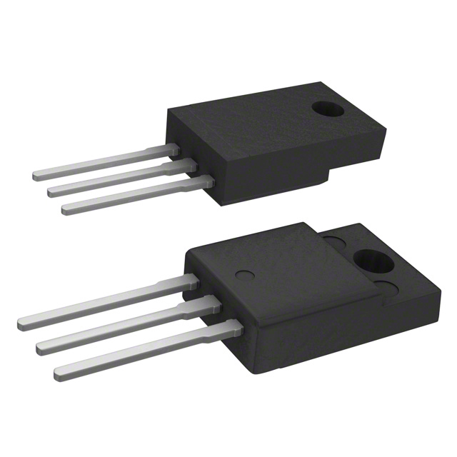
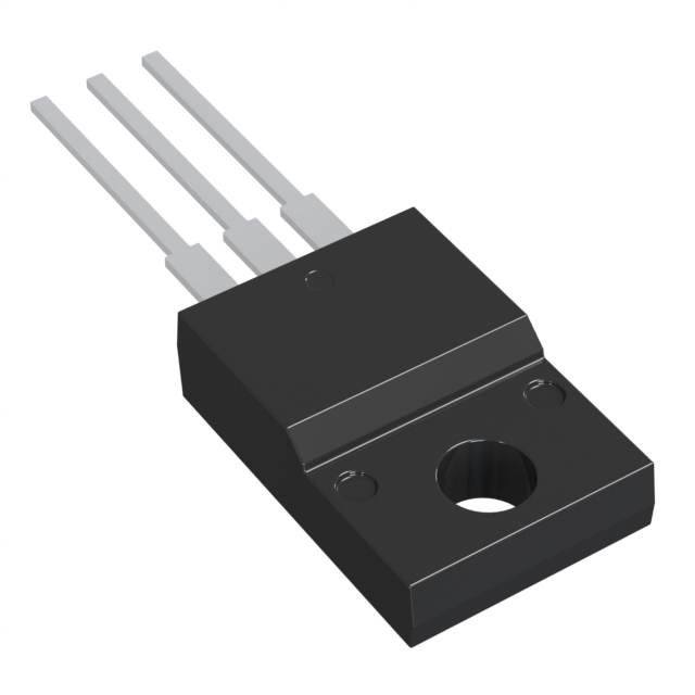
The UGF2004G is a general-purpose diode array manufactured by Taiwan Semiconductor Corporation, configured as a 1 Pair Common Cathode rectifier with 200 V reverse voltage rating and 20 A average rectified current per diode. The device is packaged in a TO-220-3 Full Pack with isolated tab for through-hole mounting applications. This part is currently in active production status with 1,060 units in stock.
Equivalent and substitute parts are identified when component availability is limited, supply chain disruptions occur, or design flexibility is required within specified electrical and mechanical parameters. Substitutes must maintain compatibility with the same package type, voltage rating, diode configuration, and thermal operating range to ensure direct replacement capability.
Substiute Parts
Key Parameters
| Parameter | Value | Unit |
|---|---|---|
| Diode Configuration | 1 Pair Common Cathode | — |
| Voltage - DC Reverse (Vr) (Max) | 200 | V |
| Current - Average Rectified (Io) (per Diode) | 20 | A |
| Voltage - Forward (Vf) (Max) @ If | 950 mV @ 10 A | — |
| Reverse Recovery Time (trr) | 20 | ns |
| Current - Reverse Leakage @ Vr | 5 | µA @ 200 V |
| Operating Temperature - Junction | -55 to 175 | °C |
| Mounting Type | Through Hole | — |
| Package / Case | TO-220-3 Full Pack, Isolated Tab | — |
| Technology | Standard | — |
| RoHS Status | ROHS3 Compliant | — |
Substitute Part Grouping Explanation
Substitute parts for the UGF2004G are qualified based on the following criteria:
Mandatory Matching Parameters:
- Diode Configuration: 1 Pair Common Cathode
- Voltage - DC Reverse (Vr) (Max): 200 V
- Package / Case: TO-220-3 Full Pack, Isolated Tab
- Mounting Type: Through Hole
- Supplier Device Package: ITO-220AB
Allowable Parameter Variations:
- Current - Average Rectified (Io) (per Diode): Equal to or greater than 20 A
- Voltage - Forward (Vf) (Max) @ If: Within acceptable forward voltage drop range for rectifier applications
- Reverse Recovery Time (trr): Fast Recovery classification (≤ 500 ns, > 200 mA)
- Current - Reverse Leakage @ Vr: Within acceptable leakage specifications
- Operating Temperature - Junction: Minimum range must encompass -55°C to 175°C or provide equivalent thermal performance
- Technology: Standard or Super Barrier technology acceptable
- RoHS and REACH Compliance: ROHS3 Compliant and REACH Unaffected required
Substitutes identified in this reference are BYVF32-200-E3/45 and SBR10200CTFP. Both parts maintain the critical electrical and mechanical parameters required for direct replacement in TO-220-3 through-hole applications.
Parameter Comparison
| Parameter | UGF2004G (Main Part) | BYVF32-200-E3/45 | SBR10200CTFP |
|---|---|---|---|
| Manufacturer | Taiwan Semiconductor Corporation | Vishay General Semiconductor - Diodes Division | Diodes Incorporated |
| Diode Configuration | 1 Pair Common Cathode | 1 Pair Common Cathode | 1 Pair Common Cathode |
| Voltage - DC Reverse (Vr) (Max) | 200 V | 200 V | 200 V |
| Current - Average Rectified (Io) (per Diode) | 20 A | 18 A | 5 A |
| Voltage - Forward (Vf) (Max) @ If | 950 mV @ 10 A | 1.15 V @ 20 A | 900 mV @ 5 A |
| Reverse Recovery Time (trr) | 20 ns | 25 ns | 20 ns |
| Current - Reverse Leakage @ Vr | 5 µA @ 200 V | 10 µA @ 200 V | 100 µA @ 200 V |
| Operating Temperature - Junction | -55 to 175 °C | -65 to 150 °C | -65 to 150 °C |
| Mounting Type | Through Hole | Through Hole | Through Hole |
| Package / Case | TO-220-3 Full Pack, Isolated Tab | TO-220-3 Full Pack, Isolated Tab | TO-220-3 Full Pack, Isolated Tab |
| Technology | Standard | Standard | Super Barrier |
| RoHS Status | ROHS3 Compliant | ROHS3 Compliant | ROHS3 Compliant |
| Product Status | Active | Active | Active |
| Inventory (Pcs) | 1,060 | 2,754 | 20,705 |
Engineering Selection Recommendations
UGF2004G (Primary Selection)
The UGF2004G remains the primary component choice when available. It provides the specified 20 A average rectified current per diode with a 200 V reverse voltage rating in a standard technology platform. The part is ROHS3 compliant, REACH unaffected, and maintains active production status. Current inventory of 1,060 units supports immediate procurement.
BYVF32-200-E3/45 (Equivalent Substitute)
The BYVF32-200-E3/45 from Vishay General Semiconductor is a direct functional equivalent with 18 A average rectified current per diode. This part maintains the same 200 V reverse voltage rating, TO-220-3 package configuration, and common cathode diode pairing. The reverse recovery time of 25 ns remains within fast recovery specifications. ROHS3 compliance and active production status are confirmed. Higher inventory availability (2,754 units) supports supply chain flexibility. The forward voltage specification of 1.15 V @ 20 A represents a minor increase compared to the main part. This substitute is suitable for applications where the 18 A current rating meets or exceeds design requirements.
SBR10200CTFP (Limited Substitution)
The SBR10200CTFP from Diodes Incorporated employs Super Barrier technology and provides 5 A average rectified current per diode at 200 V reverse voltage. This part is suitable only for applications where the current requirement does not exceed 5 A per diode. The forward voltage of 900 mV @ 5 A is favorable, and reverse recovery time of 20 ns matches the main part specification. ROHS3 compliance and active production status are confirmed. Highest inventory availability (20,705 units) provides maximum supply chain access. The elevated reverse leakage current of 100 µA @ 200 V should be evaluated against application requirements.
Frequently Asked Questions (FAQ)
Q: Can BYVF32-200-E3/45 directly replace UGF2004G in all applications?
A: BYVF32-200-E3/45 is a direct substitute when the application current requirement does not exceed 18 A per diode. Both parts share identical 200 V reverse voltage rating, TO-220-3 package configuration, common cathode diode pairing, and fast recovery characteristics. The 25 ns reverse recovery time remains within fast recovery specifications. Verify that the application design does not require the full 20 A capability of the original part.
Q: Is SBR10200CTFP suitable for high-current applications?
A: SBR10200CTFP is limited to applications requiring 5 A or less per diode. This part is not suitable for applications designed around the 20 A rating of the UGF2004G. The Super Barrier technology provides favorable forward voltage characteristics at lower current levels but does not extend the current capacity. Use this substitute only when application current requirements are confirmed below 5 A per diode.
Q: What are the package compatibility requirements for substitution?
A: All qualified substitutes maintain TO-220-3 Full Pack with isolated tab configuration for through-hole mounting. The ITO-220AB supplier device package designation is consistent across all parts. PCB footprint and thermal interface requirements remain identical. No mechanical redesign is required when substituting between qualified parts.
Q: How do forward voltage differences affect circuit performance?
A: Forward voltage variations between parts affect power dissipation and voltage drop across the rectifier. UGF2004G specifies 950 mV @ 10 A, BYVF32-200-E3/45 specifies 1.15 V @ 20 A, and SBR10200CTFP specifies 900 mV @ 5 A. Applications with tight voltage regulation requirements should evaluate forward voltage specifications at the actual operating current. Higher forward voltage increases power dissipation and may require thermal management review.
Q: Are all substitutes RoHS and REACH compliant?
A: Yes. UGF2004G, BYVF32-200-E3/45, and SBR10200CTFP are all ROHS3 compliant and REACH unaffected. All parts meet current environmental and regulatory requirements for commercial and industrial applications.
Q: What is the significance of reverse recovery time differences?
A: Reverse recovery time (trr) affects switching speed and electromagnetic interference characteristics. UGF2004G and SBR10200CTFP both specify 20 ns, while BYVF32-200-E3/45 specifies 25 ns. All values remain within fast recovery classification (≤ 500 ns, > 200 mA). The 5 ns difference is negligible for most rectifier applications and does not impact functional compatibility.
Q: Can operating temperature ranges affect substitution decisions?
A: UGF2004G specifies -55°C to 175°C junction temperature range, while BYVF32-200-E3/45 and SBR10200CTFP specify -65°C to 150°C. Applications requiring operation above 150°C require the UGF2004G. Applications operating within -55°C to 150°C range are compatible with all three parts. Verify application thermal requirements before selecting a substitute.
Q: What inventory considerations apply to part selection?
A: UGF2004G has 1,060 units in stock, BYVF32-200-E3/45 has 2,754 units, and SBR10200CTFP has 20,705 units available. Higher inventory availability for SBR10200CTFP and BYVF32-200-E3/45 supports rapid procurement when UGF2004G stock is limited. Verify current inventory status with supplier before finalizing component selection.
Alternative Parts

SJ6012L2TP
Littelfuse Inc.
6 Alternative Parts

JMK107BBJ476MA-RE
Taiyo Yuden
10 Alternative Parts

GMK107BBJ475MA-T
Taiyo Yuden
5 Alternative Parts
SJ6020N2ARP
Littelfuse Inc.
3 Alternative Parts
SJ6025R2ATP
Littelfuse Inc.
4 Alternative Parts

2474-05L
API Delevan Inc.
1 Alternative Parts

4590R-684K
API Delevan Inc.
1 Alternative Parts

CM6560R-334
API Delevan Inc.
1 Alternative Parts

CM6460-104
API Delevan Inc.
1 Alternative Parts

5526-12
API Delevan Inc.
1 Alternative Parts