


Request Quote
(Ships tomorrow)
TLE2062AID Equivalent & Substitute Parts
Part Overview
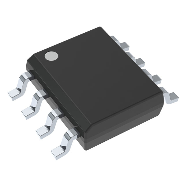
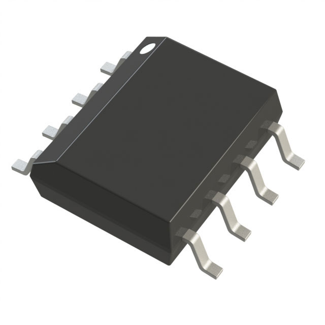
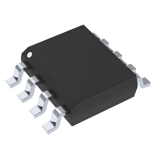
The TLE2062AID is a J-FET input operational amplifier manufactured by Texas Instruments, configured as a dual-channel (2 circuit) device in an 8-SOIC surface mount package. This component is classified as a Last Time Buy product, indicating discontinued production with limited remaining inventory (1900 Pcs). The TLE2062AID is designed for applications requiring low input bias current and low input offset voltage characteristics inherent to J-FET amplifier topology.
Identifying equivalent and substitute parts is necessary due to the Last Time Buy status of the TLE2062AID. Engineers and procurement teams must evaluate alternative components that maintain functional compatibility within the specified electrical and mechanical parameters to ensure long-term design sustainability and supply chain continuity.
Substiute Parts
Key Parameters
| Parameter | Value | Unit |
|---|---|---|
| Amplifier Type | J-FET | — |
| Number of Circuits | 2 | — |
| Slew Rate | 3.4 | V/µs |
| Gain Bandwidth Product | 2 | MHz |
| Current - Input Bias | 4 | pA |
| Voltage - Input Offset | 800 | µV |
| Current - Supply | 625 | µA (x2 Channels) |
| Current - Output / Channel | 80 | mA |
| Voltage - Supply Span (Min) | 7 | V |
| Voltage - Supply Span (Max) | 36 | V |
| Operating Temperature | -40 to 85 | °C |
| Package / Case | 8-SOIC (0.154", 3.90mm Width) | — |
| Mounting Type | Surface Mount | — |
| RoHS Status | ROHS3 Compliant | — |
Substitute Part Grouping Explanation
Substitution compatibility for the TLE2062AID is determined by the following critical parameters:
Primary Compatibility Criteria:
- Amplifier Type: J-FET topology
- Number of Circuits: 2 (dual-channel configuration)
- Package / Case: 8-SOIC form factor with 0.154" (3.90mm) width
- Mounting Type: Surface Mount
- Voltage - Supply Span: Minimum 7V to Maximum 36V overlap
- Operating Temperature Range: Minimum -40°C capability
Secondary Performance Parameters:
- Slew Rate: 3.4 V/µs (baseline reference)
- Gain Bandwidth Product: 2 MHz (baseline reference)
- Current - Input Bias: 4 pA (baseline reference)
- Voltage - Input Offset: 800 µV (baseline reference)
- Current - Supply: 625 µA per channel (baseline reference)
- Current - Output / Channel: 80 mA (baseline reference)
Substitute parts are grouped into two categories:
Category 1: Direct J-FET Substitutes (Highest Compatibility) Parts maintaining J-FET amplifier topology with identical dual-channel configuration and 8-SOIC packaging. These parts satisfy all primary compatibility criteria and represent the closest functional equivalents.
Category 2: Alternative Amplifier Type Substitutes (Conditional Compatibility) Parts with different amplifier topologies (General Purpose, Audio) but identical package, pin count, and dual-channel configuration. These require application-level verification of input bias current and offset voltage tolerance.
Parameter Comparison
| Parameter | TLE2062AID | TLE2062AIDR | AD8512ARZ | OP282GSZ | TL072CDT | NCS20072DR2G | LM833DT | OP2177ARZ |
|---|---|---|---|---|---|---|---|---|
| Manufacturer | Texas Instruments | Texas Instruments | Analog Devices Inc. | Analog Devices Inc. | STMicroelectronics | onsemi | STMicroelectronics | Analog Devices Inc. |
| Amplifier Type | J-FET | J-FET | J-FET | J-FET | J-FET | General Purpose | Audio | General Purpose |
| Number of Circuits | 2 | 2 | 2 | 2 | 2 | 2 | 2 | 2 |
| Slew Rate (V/µs) | 3.4 | 3.4 | 20 | 9 | 16 | 2.4 | 7 | 0.7 |
| Gain Bandwidth Product (MHz) | 2 | 2 | 8 | 4 | 4 | 3.2 | 15 | 1.3 |
| Current - Input Bias (pA) | 4 | 4 | 25 | 3 | 20 | 5 | 300 nA | 500 pA |
| Voltage - Input Offset (µV) | 800 | 800 | 100 | 200 | 3000 | 1300 | 300 | 15 |
| Current - Supply (µA) | 625 | 625 | 2200 | 210 | 1400 | 420 | 4000 | 400 |
| Current - Output / Channel (mA) | 80 | 80 | 70 | 10 | 40 | 65 | 37 | 10 |
| Voltage - Supply Span Min (V) | 7 | 7 | 10 | 9 | 6 | 2.7 | 5 | 5 |
| Voltage - Supply Span Max (V) | 36 | 36 | 30 | 36 | 36 | 36 | 30 | 30 |
| Operating Temperature Min (°C) | -40 | -40 | -40 | -40 | 0 | -40 | -40 | -40 |
| Operating Temperature Max (°C) | 85 | 85 | 125 | 85 | 70 | 125 | 105 | 125 |
| Package / Case | 8-SOIC | 8-SOIC | 8-SOIC | 8-SOIC | 8-SOIC | 8-SOIC | 8-SOIC | 8-SOIC |
| Product Status | Last Time Buy | Active | Active | Active | Active | Active | Active | Active |
| RoHS Status | ROHS3 Compliant | ROHS3 Compliant | ROHS3 Compliant | ROHS3 Compliant | ROHS3 Compliant | ROHS3 Compliant | ROHS3 Compliant | ROHS3 Compliant |
Engineering Selection Recommendations
Tier 1: Recommended Direct Substitutes
TLE2062AIDR (Texas Instruments) The TLE2062AIDR is the manufacturer-recommended equivalent to the TLE2062AID. This part maintains identical electrical specifications across all critical parameters: J-FET amplifier type, dual-channel configuration, 3.4 V/µs slew rate, 2 MHz gain bandwidth product, 4 pA input bias current, and 800 µV input offset voltage. The TLE2062AIDR differs only in packaging format (reel vs. tube) and product status (Active vs. Last Time Buy). This part is suitable for direct replacement in all applications where the TLE2062AID was specified. Inventory availability is significantly higher (4759 Pcs), supporting long-term supply continuity.
OP282GSZ (Analog Devices Inc.) The OP282GSZ is a J-FET amplifier with dual-channel configuration in 8-SOIC packaging. This part maintains J-FET topology and shares the same supply voltage range (9V to 36V minimum overlap with 7V to 36V). The OP282GSZ exhibits superior performance in slew rate (9 V/µs vs. 3.4 V/µs) and gain bandwidth product (4 MHz vs. 2 MHz), with lower input bias current (3 pA vs. 4 pA) and lower input offset voltage (200 µV vs. 800 µV). Supply current is reduced (210 µA vs. 625 µA), and output current per channel is lower (10 mA vs. 80 mA). The OP282GSZ is suitable for applications where the TLE2062AID output current capability is not fully utilized and where improved performance metrics are beneficial. Operating temperature range is identical (-40°C to 85°C).
Tier 2: Alternative Topology Substitutes (Conditional)
AD8512ARZ (Analog Devices Inc.) The AD8512ARZ is a J-FET amplifier with dual-channel configuration in 8-SOIC packaging. This part offers enhanced performance: 20 V/µs slew rate, 8 MHz gain bandwidth product, and 100 µV input offset voltage. However, the AD8512ARZ has higher input bias current (25 pA vs. 4 pA), higher supply current (2.2 mA vs. 625 µA), and a higher minimum supply voltage requirement (10V vs. 7V). The maximum operating temperature is extended to 125°C. This part is suitable for applications requiring higher bandwidth and faster slew rate, provided the higher supply current and input bias current are acceptable.
TL072CDT (STMicroelectronics) The TL072CDT is a J-FET amplifier with dual-channel configuration in 8-SOIC packaging, qualified to AEC-Q100 automotive standards. This part provides 16 V/µs slew rate and 4 MHz gain bandwidth product. However, the TL072CDT has significantly higher input bias current (20 pA vs. 4 pA), higher input offset voltage (3 mV vs. 800 µV), and higher supply current (1.4 mA vs. 625 µA). The operating temperature range is limited to 0°C to 70°C, which does not meet the -40°C minimum requirement of the TLE2062AID. The TL072CDT is not suitable as a direct substitute for applications requiring -40°C operation.
NCS20072DR2G (onsemi) The NCS20072DR2G is a General Purpose amplifier (not J-FET topology) with dual-channel rail-to-rail output configuration in 8-SOIC packaging. This part has lower minimum supply voltage (2.7V vs. 7V) and extended maximum operating temperature (125°C vs. 85°C). However, the NCS20072DR2G exhibits significantly different electrical characteristics: lower slew rate (2.4 V/µs vs. 3.4 V/µs), higher input bias current (5 pA vs. 4 pA), higher input offset voltage (1.3 mV vs. 800 µV), and lower output current per channel (65 mA vs. 80 mA). The different amplifier topology (General Purpose vs. J-FET) may introduce compatibility issues in applications sensitive to input bias current characteristics. This part is suitable only for applications where J-FET input characteristics are not critical.
LM833DT (STMicroelectronics) The LM833DT is an Audio amplifier (not J-FET topology) with dual-channel configuration in 8-SOIC packaging. This part has lower minimum supply voltage (5V vs. 7V) and extended maximum operating temperature (105°C vs. 85°C). However, the LM833DT exhibits significantly different electrical characteristics: higher input bias current (300 nA vs. 4 pA), lower input offset voltage (300 µV vs. 800 µV), higher supply current (4 mA vs. 625 µA), and lower output current per channel (37 mA vs. 80 mA). The different amplifier topology (Audio vs. J-FET) and substantially higher input bias current make this part unsuitable for applications requiring low input bias current characteristics.
OP2177ARZ (Analog Devices Inc.) The OP2177ARZ is a General Purpose amplifier (not J-FET topology) with dual-channel configuration in 8-SOIC packaging. This part has extended maximum operating temperature (125°C vs. 85°C). However, the OP2177ARZ exhibits significantly different electrical characteristics: much lower slew rate (0.7 V/µs vs. 3.4 V/µs), lower gain bandwidth product (1.3 MHz vs. 2 MHz), higher input bias current (500 pA vs. 4 pA), and substantially lower output current per channel (10 mA vs. 80 mA). The different amplifier topology (General Purpose vs. J-FET) and substantially reduced performance metrics make this part unsuitable for most applications where the TLE2062AID was specified.
Frequently Asked Questions (FAQ)
Q1: Can I use TLE2062AIDR as a direct replacement for TLE2062AID?
A: Yes. The TLE2062AIDR is the manufacturer-recommended equivalent with identical electrical specifications. The only differences are packaging format (reel vs. tube) and product status (Active vs. Last Time Buy). Both parts are pin-compatible in 8-SOIC configuration and maintain the same performance characteristics across all critical parameters.
Q2: What is the primary difference between J-FET and General Purpose amplifier topologies?
A: J-FET amplifiers feature extremely low input bias current (typically in the picoampere range) and are suitable for high-impedance input applications. General Purpose amplifiers typically have higher input bias current (in the nanoampere to microampere range) and are optimized for general-purpose signal conditioning. The TLE2062AID's 4 pA input bias current is characteristic of J-FET topology. Substituting with General Purpose amplifiers (NCS20072DR2G, OP2177ARZ) may introduce unacceptable bias current errors in high-impedance circuits.
Q3: Are all substitute parts available in the same 8-SOIC package?
A: Yes. All substitute parts listed are available in 8-SOIC (0.154", 3.90mm width) surface mount packaging, ensuring mechanical and electrical pin compatibility. However, packaging format (tube vs. reel) may differ. Verify packaging format requirements with your procurement specification.
Q4: Which substitute part offers the best performance improvement?
A: The AD8512ARZ offers the most significant performance enhancement with 20 V/µs slew rate (vs. 3.4 V/µs), 8 MHz gain bandwidth product (vs. 2 MHz), and 100 µV input offset voltage (vs. 800 µV). However, this part requires higher supply current (2.2 mA vs. 625 µA) and higher minimum supply voltage (10V vs. 7V). Evaluate whether these trade-offs are acceptable for your application.
Q5: Can I use TL072CDT as a substitute?
A: The TL072CDT is not recommended as a substitute for the TLE2062AID. While both are J-FET amplifiers in 8-SOIC packaging, the TL072CDT has a maximum operating temperature of only 70°C, which does not meet the TLE2062AID's -40°C to 85°C specification. Additionally, the TL072CDT exhibits higher input bias current (20 pA vs. 4 pA) and higher input offset voltage (3 mV vs. 800 µV).
Q6: What supply voltage range must I verify when selecting a substitute?
A: The TLE2062AID operates with a supply voltage range of 7V to 36V. When selecting substitutes, verify that the substitute part's supply voltage range overlaps with your application's requirements. For example, the AD8512ARZ requires a minimum of 10V, which may not be compatible with 7V to 9V supply designs. The NCS20072DR2G supports lower voltages (2.7V minimum) but may not be suitable for 36V applications due to its 36V maximum rating.
Q7: How do I determine if a substitute part is suitable for my application?
A: Evaluate substitutes based on the following hierarchy: (1) Verify package compatibility (8-SOIC form factor); (2) Confirm supply voltage range overlap; (3) Verify operating temperature range includes your application requirements; (4) Compare input bias current and input offset voltage if your application uses high-impedance inputs; (5) Compare slew rate and gain bandwidth product if your application requires specific frequency response; (6) Compare output current capability if your application drives low-impedance loads; (7) Verify RoHS and compliance status matches your requirements.
Q8: Is inventory availability a factor in substitute selection?
A: Yes. The TLE2062AID has Last Time Buy status with limited inventory (1900 Pcs). The TLE2062AIDR (4759 Pcs), OP282GSZ (25333 Pcs), and TL072CDT (203200 Pcs) have significantly higher inventory levels, supporting long-term supply continuity. Consider inventory availability when planning production schedules and design transitions.
Q9: Do all substitute parts have the same RoHS and REACH compliance status?
A: Yes. All substitute parts listed are ROHS3 Compliant and REACH Unaffected, matching the TLE2062AID's compliance status. All parts are classified under ECCN EAR99 and HTSUS 8542.33.0001.
Q10: Can I mix TLE2062AID and substitute parts in the same production batch?
A: Mixing different part numbers in the same production batch is not recommended due to potential performance variations. While substitute parts maintain functional compatibility, electrical parameter variations (particularly slew rate, gain bandwidth product, and input offset voltage) may introduce measurable differences in circuit performance. Maintain design consistency by using a single part number per design revision.
Alternative Parts

SJ6012L2TP
Littelfuse Inc.
6 Alternative Parts

JMK107BBJ476MA-RE
Taiyo Yuden
10 Alternative Parts

GMK107BBJ475MA-T
Taiyo Yuden
5 Alternative Parts
SJ6020N2ARP
Littelfuse Inc.
3 Alternative Parts
SJ6025R2ATP
Littelfuse Inc.
4 Alternative Parts

2474-05L
API Delevan Inc.
1 Alternative Parts

4590R-684K
API Delevan Inc.
1 Alternative Parts

CM6560R-334
API Delevan Inc.
1 Alternative Parts

CM6460-104
API Delevan Inc.
1 Alternative Parts

5526-12
API Delevan Inc.
1 Alternative Parts