


Request Quote
(Ships tomorrow)
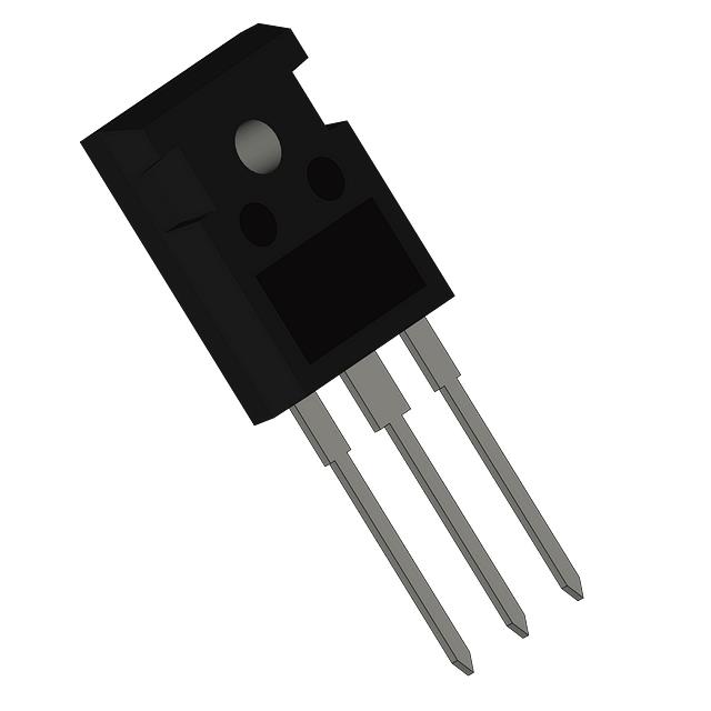
STW28NK60Z Equivalent & Substitute Parts
Part Overview
The STW28NK60Z is an N-Channel 600V 27A MOSFET manufactured by STMicroelectronics in the SuperMESH™ series, housed in a TO-247-3 through-hole package. This device is rated for 350W power dissipation and operates across a temperature range of -55°C to 150°C. The part is currently classified as obsolete, necessitating identification of functionally equivalent alternatives for ongoing design support and production continuity.
Substiute Parts
Key Parameters
| Parameter | Value | Unit |
|---|---|---|
| Drain to Source Voltage (Vdss) | 600 | V |
| Continuous Drain Current (Id) @ 25°C | 27 | A |
| Rds On (Max) @ 13.5A, 10V | 185 | mOhm |
| Gate Threshold Voltage (Vgs(th)) @ 150µA | 4.5 | V |
| Gate Charge (Qg) @ 10V | 264 | nC |
| Power Dissipation (Max) | 350 | W |
| Operating Temperature Range | -55 to 150 | °C |
| Package Type | TO-247-3 | — |
| Mounting Type | Through Hole | — |
Substitute Part Grouping Explanation
Substitution of the STW28NK60Z is determined by strict alignment of electrical and mechanical parameters. The primary substitution criteria are:
Critical Parameters for Substitution:
- Drain to Source Voltage (Vdss): 600V minimum
- Continuous Drain Current (Id): 27A or greater
- Package Type: TO-247-3 or compatible TO-247 variant
- Mounting Type: Through Hole
- Operating Temperature Range: -55°C to 150°C minimum
Secondary Compatibility Factors:
- Rds On (Max): Lower or equivalent values indicate improved performance
- Gate Charge (Qg): Lower values reduce switching losses
- Power Dissipation: Higher ratings provide design margin
Substitute parts are grouped into two categories:
Category A – Direct Equivalents (27A @ 600V): Parts meeting or exceeding the exact current rating at 600V with comparable Rds On characteristics. These include IRFP27N60KPBF and IRFP27N60K.
Category B – Higher Current Alternatives (≥36A @ 600V): Parts with elevated current ratings that provide enhanced thermal and electrical margin. These include APT34F60B and APT34M60B, suitable for applications requiring additional current capacity.
Category C – Lower Current Alternatives (21-22A @ 600V): Parts with reduced current ratings that maintain 600V voltage rating. These include IPW60R165CPFKSA1, IRFP22N60KPBF, and FCH170N60, applicable where current requirements are lower than the original specification.
Parameter Comparison
| Part Number | Manufacturer | Vdss (V) | Id @ 25°C (A) | Rds On Max (mOhm) | Qg @ 10V (nC) | Power Diss. (W) | Package | Status |
|---|---|---|---|---|---|---|---|---|
| STW28NK60Z | STMicroelectronics | 600 | 27 | 185 | 264 | 350 | TO-247-3 | Obsolete |
| IRFP27N60KPBF | Vishay Siliconix | 600 | 27 | 220 | 180 | 500 | TO-247-3 | Active |
| IRFP27N60K | Vishay Siliconix | 600 | 27 | 220 | 180 | 500 | TO-247-3 | Active |
| IRFP26N60LPBF | Vishay Siliconix | 600 | 26 | 250 | 180 | 470 | TO-247-3 | Active |
| APT34F60B | Microchip Technology | 600 | 36 | 210 | 165 | 624 | TO-247-3 | Active |
| APT34M60B | Microchip Technology | 600 | 36 | 190 | 165 | 624 | TO-247-3 | Active |
| IRFP22N60KPBF | Vishay Siliconix | 600 | 22 | 280 | 150 | 370 | TO-247-3 | Active |
| FCH170N60 | Fairchild Semiconductor | 600 | 22 | 170 | 55 | 227 | TO-247-3 | Active |
| IPW60R165CPFKSA1 | Infineon Technologies | 600 | 21 | 165 | 52 | 192 | TO-247-3 | Not For New Designs |
| IXFH26N60P | IXYS | 600 | 26 | 270 | 72 | 460 | TO-247-3 | Active |
| IPW65R190C7XKSA1 | Infineon Technologies | 650 | 13 | 190 | 23 | 72 | TO-247-3 | Active |
Engineering Selection Recommendations
Primary Substitutes (Direct Equivalents):
IRFP27N60KPBF and IRFP27N60K are the preferred direct substitutes for the STW28NK60Z. Both devices are manufactured by Vishay Siliconix and maintain the identical 27A continuous drain current at 600V. These parts are in active production status with ROHS3 compliance and REACH unaffected certification. The IRFP27N60KPBF variant includes tube packaging and is available in high inventory (16,963 units). While Rds On is slightly higher at 220mOhm compared to the original 185mOhm, power dissipation capability is enhanced at 500W, providing additional thermal margin.
Secondary Substitutes (Higher Current Capacity):
APT34M60B and APT34F60B from Microchip Technology provide 36A continuous drain current at 600V, offering increased current capacity and improved Rds On performance (190mOhm and 210mOhm respectively). These devices are in active production with ROHS3 compliance. The APT34M60B is part of the POWER MOS 8™ series and delivers superior power dissipation at 624W. These substitutes are suitable for applications where current headroom is required.
Alternative Substitutes (Lower Current Capacity):
IRFP22N60KPBF, FCH170N60, and IPW60R165CPFKSA1 operate at reduced current ratings (22A, 22A, and 21A respectively) while maintaining 600V voltage rating. These are applicable only where design current requirements are lower than the original 27A specification. IPW60R165CPFKSA1 carries a "Not For New Designs" status and should be avoided for new applications.
Voltage Variant:
IPW65R190C7XKSA1 operates at 650V with 13A current rating and is not suitable as a direct substitute due to significantly reduced current capacity.
Compliance Considerations:
All recommended primary and secondary substitutes maintain ROHS3 compliance and REACH unaffected status, ensuring regulatory alignment with the original part. Packaging variants (tube vs. bulk) do not affect electrical compatibility.
Frequently Asked Questions (FAQ)
Q: Can IRFP27N60KPBF directly replace STW28NK60Z in existing designs?
A: Yes. IRFP27N60KPBF is a direct electrical and mechanical equivalent with identical 27A @ 600V ratings, TO-247-3 package, and -55°C to 150°C operating range. The slightly higher Rds On (220mOhm vs. 185mOhm) results in marginally increased conduction losses, offset by superior power dissipation capability (500W vs. 350W). No circuit modifications are required.
Q: What is the difference between IRFP27N60K and IRFP27N60KPBF?
A: Both devices are electrically identical with 27A @ 600V specifications. IRFP27N60KPBF includes tube packaging and carries ROHS3 compliance certification. IRFP27N60K does not specify packaging type and carries RoHS non-compliant status. For new designs and regulated applications, IRFP27N60KPBF is the preferred variant.
Q: Are APT34F60B and APT34M60B interchangeable?
A: Both devices share identical electrical specifications (36A @ 600V, 600V Vdss, TO-247-3 package, -55°C to 150°C range). APT34M60B belongs to the POWER MOS 8™ series and exhibits lower Rds On (190mOhm vs. 210mOhm). For applications sensitive to conduction losses, APT34M60B is preferred. Both are in active production with ROHS3 compliance.
Q: Can I use a 36A device (APT34M60B) in place of a 27A device (STW28NK60Z)?
A: Yes. Higher current-rated devices are suitable substitutes provided all other parameters (voltage, package, temperature range) are met. The 36A device provides additional current margin and thermal headroom. No circuit modifications are required. This substitution is conservative from a current capacity perspective.
Q: Why is IPW60R165CPFKSA1 marked "Not For New Designs"?
A: This status indicates the part is in mature or declining production phase. While functionally operational, Infineon does not recommend this device for new circuit designs. For new applications, select from active production alternatives such as IRFP27N60KPBF or APT34M60B.
Q: What is the significance of lower gate charge (Qg) in substitute parts?
A: Gate charge directly affects switching speed and driver power requirements. Lower Qg values (e.g., FCH170N60 at 55nC vs. STW28NK60Z at 264nC) reduce switching losses and simplify gate driver design. However, lower Qg does not affect DC conduction characteristics or thermal performance. Selection depends on switching frequency and driver capability.
Q: Are all substitute parts ROHS3 compliant?
A: No. IRFP27N60K is RoHS non-compliant. All other recommended substitutes (IRFP27N60KPBF, APT34F60B, APT34M60B, IRFP22N60KPBF, FCH170N60, IPW60R165CPFKSA1, IXFH26N60P, and IPW65R190C7XKSA1) carry ROHS3 compliance certification. For regulated applications, verify compliance requirements before selection.
Q: Can I use FCH170N60 as a substitute despite its lower 22A rating?
A: FCH170N60 is suitable only if your application current requirement is 22A or lower. The device exhibits superior Rds On (170mOhm) and significantly lower gate charge (55nC), making it advantageous for low-current, high-frequency switching applications. If your design requires the full 27A capacity of the original part, this substitute is not appropriate.
Q: What is the thermal performance difference between STW28NK60Z and its substitutes?
A: Power dissipation ratings vary: STW28NK60Z (350W), IRFP27N60KPBF (500W), APT34M60B (624W), and FCH170N60 (227W). Higher power dissipation ratings indicate superior thermal capability under identical operating conditions. Selection should account for heatsink availability and thermal design requirements. Lower Rds On values reduce conduction losses and improve thermal performance.
Q: Are package variants (TO-247-3 vs. TO-247AC vs. TO-247AD) interchangeable?
A: All listed variants (TO-247-3, TO-247AC, TO-247AD, TO-247 [B]) are mechanically compatible through-hole packages with identical pin configurations and mounting footprints. Electrical performance is independent of package variant designation. PCB layouts and heatsink mounting are directly compatible across all variants.
Alternative Parts

SJ6012L2TP
Littelfuse Inc.
6 Alternative Parts

JMK107BBJ476MA-RE
Taiyo Yuden
10 Alternative Parts

GMK107BBJ475MA-T
Taiyo Yuden
5 Alternative Parts
SJ6020N2ARP
Littelfuse Inc.
3 Alternative Parts
SJ6025R2ATP
Littelfuse Inc.
4 Alternative Parts

2474-05L
API Delevan Inc.
1 Alternative Parts

4590R-684K
API Delevan Inc.
1 Alternative Parts

CM6560R-334
API Delevan Inc.
1 Alternative Parts

CM6460-104
API Delevan Inc.
1 Alternative Parts

5526-12
API Delevan Inc.
1 Alternative Parts