


Request Quote
(Ships tomorrow)
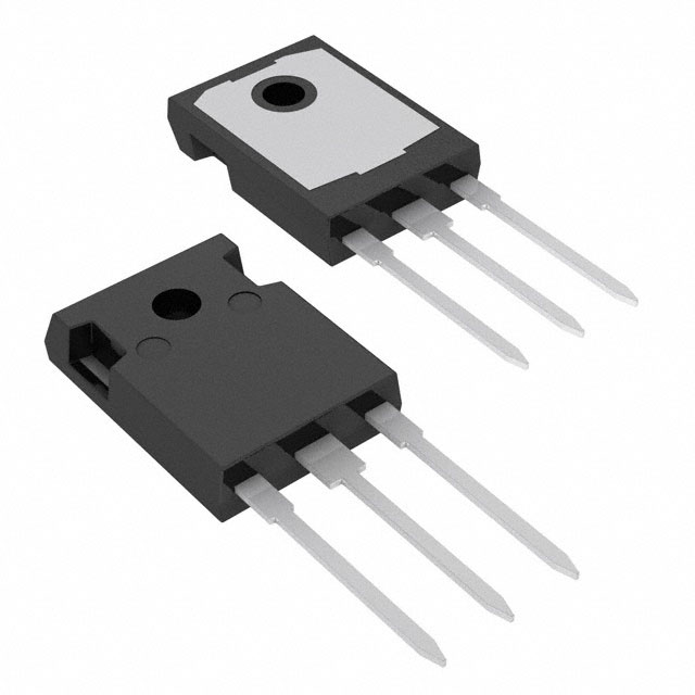
MBR3045PT Equivalent & Substitute Parts
Part Overview
The MBR3045PT is a Schottky diode array in a 1 Pair Common Cathode configuration rated for 45 V DC reverse voltage and 30 A average rectified current per diode. Manufactured by Diodes Incorporated, this component is packaged in TO-3P-3 (SC-65-3) through-hole format and features fast recovery characteristics with a maximum forward voltage of 760 mV at 30 A.
The MBR3045PT is classified as obsolete. Equivalent and substitute parts are necessary to maintain design continuity and ensure component availability for new production builds and field replacements. Substitute components must maintain electrical compatibility across voltage, current, and thermal specifications while accommodating package and mounting variations.
Substiute Parts
Key Parameters
| Parameter | Value | Unit |
|---|---|---|
| Diode Configuration | 1 Pair Common Cathode | — |
| Technology | Schottky | — |
| Voltage - DC Reverse (Vr) (Max) | 45 | V |
| Current - Average Rectified (Io) (per Diode) | 30 | A |
| Voltage - Forward (Vf) (Max) @ If | 760 mV @ 30 A | — |
| Speed | Fast Recovery ≤ 500ns, > 200mA (Io) | — |
| Current - Reverse Leakage @ Vr | 1 | mA @ 45 V |
| Operating Temperature - Junction | -65 to 150 | °C |
| Mounting Type | Through Hole | — |
| Package / Case | TO-3P-3, SC-65-3 | — |
| RoHS Status | ROHS3 Compliant | — |
Substitute Part Grouping Explanation
Substitution of the MBR3045PT is determined by the following critical parameters:
Mandatory Compatibility Criteria:
- Diode Configuration: 1 Pair Common Cathode
- Technology: Schottky
- Voltage - DC Reverse (Vr) (Max): 45 V minimum
- Current - Average Rectified (Io) (per Diode): 30 A minimum
- Mounting Type: Through Hole
- Speed: Fast Recovery ≤ 500ns, > 200mA (Io)
Acceptable Variations:
- Package / Case: TO-3P-3, SC-65-3, TO-247-3, or TO-247AD (all through-hole formats)
- Voltage - Forward (Vf): Variations permitted within design margin
- Current - Reverse Leakage: Variations permitted within design margin
- Operating Temperature - Junction: Variations permitted if minimum -55°C and maximum ≥ 150°C
Substitute parts are grouped into two categories: Direct Equivalents (matching 30 A current rating) and Functional Alternatives (lower current ratings suitable for reduced-load applications).
Parameter Comparison
| Part Number | Manufacturer | Vr (Max) [V] | Io (per Diode) [A] | Vf (Max) [mV] | Ir @ Vr [mA/µA] | Tj (Max) [°C] | Package | Product Status |
|---|---|---|---|---|---|---|---|---|
| MBR3045PT | Diodes Incorporated | 45 | 30 | 760 @ 30 A | 1 mA @ 45 V | 150 | TO-3P-3 | Obsolete |
| MBR3045PT-E3/45 | Vishay General Semiconductor | 45 | 30 | 760 @ 30 A | 1 mA @ 45 V | 150 | TO-247AD | Active |
| STPS60L45CW | STMicroelectronics | 45 | 30 | 550 @ 30 A | 1.5 mA @ 45 V | 150 | TO-247-3 | Active |
| STPS4045CWY | STMicroelectronics | 45 | 20 | 760 @ 20 A | 200 µA @ 45 V | 175 | TO-247-3 | Active |
| MBR3045WTP | SMC Diode Solutions | 45 | — | 700 @ 15 A | 1 mA @ 45 V | 150 | TO-247AD | Active |
| 30CPQ045 | SMC Diode Solutions | 45 | — | 540 @ 15 A | 1 mA @ 45 V | 150 | TO-247AD | Active |
| STPS30L45CW | STMicroelectronics | 45 | 15 | 550 @ 15 A | 400 µA @ 45 V | 150 | TO-247-3 | Active |
| STPS3045CW | STMicroelectronics | 45 | 15 | 570 @ 15 A | 200 µA @ 45 V | 200 | TO-247-3 | Active |
| MBR3045WT | Vishay General Semiconductor | 45 | 15 | 760 @ 30 A | 1 mA @ 45 V | 150 | TO-247AC | Obsolete |
Engineering Selection Recommendations
Primary Substitute (Direct Equivalent):
MBR3045PT-E3/45 (Vishay General Semiconductor) is the recommended direct substitute. This part maintains identical electrical specifications: 45 V reverse voltage, 30 A average rectified current, 760 mV forward voltage at 30 A, and -65°C to 150°C operating temperature range. The component is Active in product status and ROHS3 compliant. Package variation from TO-3P-3 to TO-247AD requires PCB layout verification for pin compatibility.
STPS60L45CW (STMicroelectronics) provides equivalent current handling at 30 A with improved forward voltage characteristics (550 mV at 30 A versus 760 mV). This part is Active and ROHS3 compliant. Operating temperature maximum is 150°C, matching the original specification.
Secondary Substitutes (Reduced Current Rating):
STPS4045CWY (STMicroelectronics) is rated for 20 A average rectified current and is suitable for applications where load current does not exceed 20 A. This part features extended operating temperature range (-40°C to 175°C) and carries AEC-Q101 automotive qualification. ROHS3 compliant and Active status.
STPS30L45CW, STPS3045CW, MBR3045WTP, and 30CPQ045 are rated for 15 A average rectified current and are suitable only for applications where load current does not exceed 15 A. All are Active in product status and ROHS3 compliant.
Compliance Considerations:
All recommended substitutes are ROHS3 compliant. MBR3045WT (Vishay) is RoHS non-compliant and should not be selected for new designs requiring RoHS compliance.
Frequently Asked Questions (FAQ)
Q: Can MBR3045PT-E3/45 be used as a direct replacement for MBR3045PT?
A: MBR3045PT-E3/45 maintains all critical electrical specifications: 45 V reverse voltage, 30 A average rectified current, 760 mV forward voltage at 30 A, and identical operating temperature range. The package changes from TO-3P-3 to TO-247AD, requiring verification of PCB footprint compatibility and thermal management provisions. Both are through-hole components with equivalent mounting requirements.
Q: What is the difference between STPS60L45CW and MBR3045PT?
A: Both components are rated for 45 V reverse voltage and 30 A average rectified current. STPS60L45CW features lower forward voltage (550 mV at 30 A versus 760 mV), resulting in reduced power dissipation. The package format differs (TO-247-3 versus TO-3P-3). STPS60L45CW is Active in product status, while MBR3045PT is Obsolete.
Q: Can STPS4045CWY replace MBR3045PT in all applications?
A: STPS4045CWY is rated for 20 A average rectified current, which is lower than the MBR3045PT specification of 30 A. This substitute is suitable only for applications where the maximum load current does not exceed 20 A. STPS4045CWY provides extended operating temperature range (-40°C to 175°C) and automotive qualification (AEC-Q101).
Q: Are 15 A rated parts (STPS30L45CW, STPS3045CW, 30CPQ045, MBR3045WTP) suitable substitutes?
A: 15 A rated parts are suitable only for applications where the maximum load current does not exceed 15 A. These components maintain the 45 V reverse voltage specification and Schottky technology. Selection among these parts should be based on forward voltage characteristics, reverse leakage current, and operating temperature requirements specific to the application.
Q: What package considerations apply when substituting MBR3045PT?
A: MBR3045PT uses TO-3P-3 (SC-65-3) package. Substitutes employ TO-247-3 or TO-247AD packages. All are through-hole formats with different pin configurations and thermal characteristics. PCB layout modifications are required. Verify pin assignment, lead spacing, and thermal pad design before implementation.
Q: Is RoHS compliance a factor in selecting substitutes?
A: Yes. MBR3045PT is ROHS3 compliant. MBR3045WT (Vishay) is RoHS non-compliant and should not be selected for new designs or applications requiring RoHS compliance. All other listed substitutes are ROHS3 compliant.
Q: How do forward voltage differences affect substitute selection?
A: Forward voltage variations among substitutes range from 540 mV to 760 mV at rated current. Lower forward voltage reduces power dissipation and heat generation. Selection should account for circuit design margins, thermal management capability, and efficiency requirements. Verify that the selected part's forward voltage characteristics are compatible with the application's voltage regulation and power budget.
Alternative Parts

SJ6012L2TP
Littelfuse Inc.
6 Alternative Parts

JMK107BBJ476MA-RE
Taiyo Yuden
10 Alternative Parts

GMK107BBJ475MA-T
Taiyo Yuden
5 Alternative Parts
SJ6020N2ARP
Littelfuse Inc.
3 Alternative Parts
SJ6025R2ATP
Littelfuse Inc.
4 Alternative Parts

2474-05L
API Delevan Inc.
1 Alternative Parts

4590R-684K
API Delevan Inc.
1 Alternative Parts

CM6560R-334
API Delevan Inc.
1 Alternative Parts

CM6460-104
API Delevan Inc.
1 Alternative Parts

5526-12
API Delevan Inc.
1 Alternative Parts