


Request Quote
(Ships tomorrow)
MBR10200CT Equivalent & Substitute Parts
Part Overview
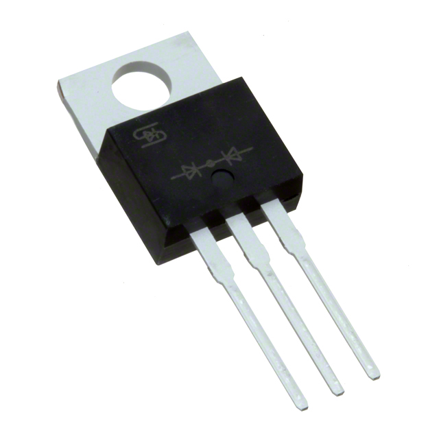
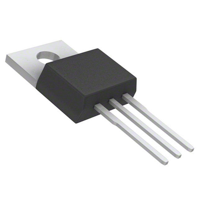
The MBR10200CT is a Schottky diode array in a 1 Pair Common Cathode configuration, rated for 200 V DC reverse voltage and 10 A average rectified current per diode. Manufactured by Taiwan Semiconductor Corporation, this component is packaged in TO-220-3 through-hole format and maintains Active product status. The device is ROHS3 compliant with Moisture Sensitivity Level 1 (Unlimited).
Equivalent and substitute parts are identified when design requirements necessitate alternative sourcing due to inventory constraints, manufacturer availability, or specific performance characteristics within the allowed electrical and mechanical parameter ranges for this diode category.
Substiute Parts
Key Parameters
| Parameter | Value |
|---|---|
| Diode Configuration | 1 Pair Common Cathode |
| Technology | Schottky |
| Voltage - DC Reverse (Vr) (Max) | 200 V |
| Current - Average Rectified (Io) (per Diode) | 10 A |
| Voltage - Forward (Vf) (Max) @ If | 980 mV @ 10 A |
| Speed | Fast Recovery ≤ 500ns, > 200mA (Io) |
| Current - Reverse Leakage @ Vr | 100 µA @ 200 V |
| Operating Temperature - Junction | -55°C ~ 150°C |
| Mounting Type | Through Hole |
| Package / Case | TO-220-3 |
| RoHS Status | ROHS3 Compliant |
| Moisture Sensitivity Level (MSL) | 1 (Unlimited) |
Substitute Part Grouping Explanation
Substitute parts for the MBR10200CT are grouped based on strict electrical and mechanical compatibility within the Schottky diode array category. The primary substitution criteria are:
Critical Parameters for Substitution:
- Diode Configuration: 1 Pair Common Cathode (mandatory match)
- Technology: Schottky (mandatory match)
- Voltage - DC Reverse (Vr) (Max): 200 V (mandatory match)
- Mounting Type: Through Hole (mandatory match)
- Package / Case: TO-220-3 (mandatory match)
Secondary Parameters Allowing Variation:
- Current - Average Rectified (Io) (per Diode): Substitutes rated at 5 A, 10 A, 15 A, or 20 A are acceptable when the application current requirement does not exceed the substitute rating
- Voltage - Forward (Vf) (Max) @ If: Variation permitted within Schottky diode specifications
- Current - Reverse Leakage @ Vr: Variation permitted within acceptable leakage ranges
- Operating Temperature - Junction: Variation permitted when application temperature range is within substitute limits
All substitute parts listed maintain ROHS3 compliance, MSL 1 (Unlimited), and Active product status.
Parameter Comparison
| Part Number | Manufacturer | Io (per Diode) | Vf (Max) @ If | Reverse Leakage @ 200V | Operating Temp (Junction) | Packaging | Inventory Status |
|---|---|---|---|---|---|---|---|
| MBR10200CT | Taiwan Semiconductor Corporation | 10 A | 980 mV @ 10 A | 100 µA | -55°C ~ 150°C | TO-220AB | 45200 Pcs |
| MBR10200CT-G1 | Diodes Incorporated | 5 A | 950 mV @ 5 A | 150 µA | -55°C ~ 150°C | TO-220-3 | 15203 Pcs |
| MBR20200CT-BP | Micro Commercial Co | 20 A | 950 mV @ 10 A | 50 µA | -55°C ~ 150°C | TO-220AB | 3405 Pcs |
| MBR20200CT-G1 | Diodes Incorporated | 10 A | 900 mV @ 10 A | 50 µA | -65°C ~ 150°C | TO-220-3 | 5886 Pcs |
| V20200C-E3/4W | Vishay General Semiconductor - Diodes Division | 10 A | 1.6 V @ 10 A | 150 µA | -40°C ~ 150°C | TO-220-3 | 19100 Pcs |
| V20202C-M3/4W | Vishay General Semiconductor - Diodes Division | 10 A | 900 mV @ 10 A | 150 µA | -40°C ~ 175°C | TO-220-3 | 6190 Pcs |
| V30200C-E3/4W | Vishay General Semiconductor - Diodes Division | 15 A | 1.1 V @ 15 A | 160 µA | -40°C ~ 150°C | TO-220-3 | 17400 Pcs |
| V30202C-M3/4W | Vishay General Semiconductor - Diodes Division | 15 A | 880 mV @ 15 A | 250 µA | -40°C ~ 175°C | TO-220-3 | 8487 Pcs |
Engineering Selection Recommendations
Direct Equivalent (Identical Specifications): MBR10200CT (Taiwan Semiconductor Corporation) is the direct equivalent to itself and serves as the reference baseline for all substitution comparisons.
Recommended Substitutes for Current-Matched Applications (10 A):
MBR20200CT-G1 (Diodes Incorporated) provides identical 10 A current rating with improved forward voltage characteristics (900 mV vs. 980 mV @ 10 A) and extended lower temperature operating range (-65°C vs. -55°C minimum). This part maintains ROHS3 compliance and Active product status.
V20202C-M3/4W (Vishay General Semiconductor - Diodes Division, TMBS® series) offers 10 A current rating with optimized forward voltage (900 mV @ 10 A) and extended upper temperature capability (-40°C ~ 175°C). ROHS3 compliant and Active status.
Substitutes for Higher Current Applications (≥ 15 A):
MBR20200CT-BP (Micro Commercial Co) provides 20 A current rating, suitable for applications requiring higher current capacity. Forward voltage is 950 mV @ 10 A with reduced reverse leakage (50 µA). ROHS3 compliant and Active status.
V30200C-E3/4W and V30202C-M3/4W (Vishay General Semiconductor - Diodes Division, TMBS® series) both provide 15 A current rating for applications requiring intermediate current capacity. V30202C-M3/4W offers superior forward voltage characteristics (880 mV @ 15 A) and extended temperature range (-40°C ~ 175°C). Both ROHS3 compliant and Active status.
Substitutes for Lower Current Applications (5 A):
MBR10200CT-G1 (Diodes Incorporated) provides 5 A current rating, suitable for applications with reduced current requirements. ROHS3 compliant and Active status.
All recommended substitutes maintain the mandatory electrical and mechanical parameters: 200 V DC reverse voltage, Schottky technology, 1 Pair Common Cathode configuration, Through Hole mounting, and TO-220-3 package format.
Frequently Asked Questions (FAQ)
Q: Can MBR10200CT-G1 (5 A) be used as a substitute for MBR10200CT (10 A)?
A: MBR10200CT-G1 is suitable only for applications where the maximum required current does not exceed 5 A. The 10 A rating of the original MBR10200CT cannot be achieved with the 5 A substitute. Verify application current requirements before selection.
Q: What is the difference between MBR20200CT-BP and MBR20200CT-G1?
A: Both parts provide 200 V reverse voltage and Schottky technology in TO-220-3 package. MBR20200CT-BP (Micro Commercial Co) is rated for 20 A current, while MBR20200CT-G1 (Diodes Incorporated) is rated for 10 A. MBR20200CT-G1 offers lower forward voltage (900 mV vs. 950 mV @ 10 A) and reduced reverse leakage (50 µA vs. 50 µA). Selection depends on required current capacity.
Q: Are Vishay TMBS® series parts (V20202C-M3/4W, V30202C-M3/4W) compatible with the MBR10200CT?
A: Yes. Both Vishay parts maintain the mandatory parameters: 200 V reverse voltage, Schottky technology, 1 Pair Common Cathode configuration, Through Hole mounting, and TO-220-3 package. V20202C-M3/4W matches the 10 A current rating with improved forward voltage (900 mV @ 10 A) and extended temperature range (-40°C ~ 175°C). V30202C-M3/4W provides 15 A current rating with optimized forward voltage (880 mV @ 15 A).
Q: What is the significance of forward voltage (Vf) differences between substitute parts?
A: Forward voltage variation affects power dissipation and thermal performance in the application circuit. Lower forward voltage (e.g., 880 mV vs. 980 mV) reduces power loss and heat generation. Selection should consider application thermal requirements and power budget constraints.
Q: Can higher-rated current parts (15 A, 20 A) be used in applications designed for 10 A?
A: Yes. Higher current-rated parts are suitable for 10 A applications. The higher rating provides additional design margin and thermal headroom. Verify that package dimensions and thermal characteristics remain compatible with the application PCB layout and cooling provisions.
Q: What is the difference between TO-220AB and TO-220-3 packaging?
A: Both designations refer to the same TO-220-3 physical package format with three leads suitable for Through Hole mounting. The designations are manufacturer-specific nomenclature variations. All listed parts are mechanically compatible in TO-220-3 footprints.
Q: Are all substitute parts ROHS3 compliant?
A: Yes. All substitute parts listed maintain ROHS3 compliance and Moisture Sensitivity Level 1 (Unlimited), matching the original MBR10200CT specifications.
Q: What operating temperature range should be selected for thermal design?
A: The MBR10200CT operates from -55°C to 150°C junction temperature. Substitute parts offer varying ranges: MBR10200CT-G1 and MBR20200CT-G1 extend to -65°C minimum; Vishay TMBS® series parts extend to -40°C minimum and 175°C maximum. Select the substitute whose operating range encompasses the application's thermal environment.
Alternative Parts

SJ6012L2TP
Littelfuse Inc.
6 Alternative Parts

JMK107BBJ476MA-RE
Taiyo Yuden
10 Alternative Parts

GMK107BBJ475MA-T
Taiyo Yuden
5 Alternative Parts
SJ6020N2ARP
Littelfuse Inc.
3 Alternative Parts
SJ6025R2ATP
Littelfuse Inc.
4 Alternative Parts

2474-05L
API Delevan Inc.
1 Alternative Parts

4590R-684K
API Delevan Inc.
1 Alternative Parts

CM6560R-334
API Delevan Inc.
1 Alternative Parts

CM6460-104
API Delevan Inc.
1 Alternative Parts

5526-12
API Delevan Inc.
1 Alternative Parts