


Request Quote
(Ships tomorrow)
IXFV20N80P N-Channel 800V 20A MOSFET Equivalent & Substitute Parts
Part Overview
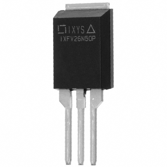
The IXFV20N80P is an N-Channel 800V 20A MOSFET manufactured by IXYS in the HiPerFET™ series, housed in a PLUS220 through-hole package. This device is classified as obsolete, making identification of equivalent and substitute parts essential for ongoing design support and production continuity. The IXFV20N80P delivers 500W maximum power dissipation and operates across a temperature range of -55°C to 150°C, serving applications requiring high-voltage switching and power conversion.
Substiute Parts
Key Parameters
| Parameter | Value | Unit |
|---|---|---|
| Drain to Source Voltage (Vdss) | 800 | V |
| Continuous Drain Current (Id) @ 25°C | 20 | A |
| On-State Resistance (Rds On) @ 10A, 10V | 520 | mOhm |
| Gate Threshold Voltage (Vgs(th)) @ 4mA | 5 | V |
| Gate Charge (Qg) @ 10V | 86 | nC |
| Maximum Gate Voltage (Vgs) | ±30 | V |
| Input Capacitance (Ciss) @ 25V | 4685 | pF |
| Power Dissipation (Max) | 500 | W |
| Operating Temperature Range | -55 to 150 | °C |
| Package Type | TO-220-3, Short Tab | — |
| Mounting Type | Through Hole | — |
| RoHS Status | ROHS3 Compliant | — |
Substitute Part Grouping Explanation
Substitution of the IXFV20N80P is determined by strict alignment of electrical and mechanical parameters within the N-Channel MOSFET category. The following criteria establish valid substitution relationships:
Primary Electrical Criteria:
- Drain to Source Voltage (Vdss): Must equal 800V
- Continuous Drain Current (Id): Must meet or exceed 20A at 25°C
- On-State Resistance (Rds On): Lower or equivalent values acceptable
- Gate Threshold Voltage (Vgs(th)): Must be compatible with 10V drive voltage
- Maximum Gate Voltage (Vgs): Must accommodate ±30V or greater
- Operating Temperature Range: Must span -55°C to 150°C minimum
Mechanical Criteria:
- Mounting Type: Through Hole required
- Package Compatibility: TO-220 family packages acceptable with PCB layout verification
Compliance Criteria:
- RoHS3 Compliance: Required
- REACH Status: Unaffected required
Substitute parts are grouped based on current rating capability and package form factor. Parts with current ratings below 20A are listed as partial substitutes requiring application-level verification. Parts with enhanced current ratings (23A and above) provide direct substitution with improved thermal headroom.
Parameter Comparison
| Parameter | IXFV20N80P | APT22F80B | R8010ANX | SPP11N80C3XKSA1 | STP13N80K5 |
|---|---|---|---|---|---|
| Manufacturer | IXYS | Microchip Technology | Rohm Semiconductor | Infineon Technologies | STMicroelectronics |
| Vdss (V) | 800 | 800 | 800 | 800 | 800 |
| Id @ 25°C (A) | 20 | 23 | 10 | 11 | 12 |
| Rds On @ 10V (mOhm) | 520 @ 10A | 500 @ 12A | 560 @ 5A | 450 @ 7.1A | 450 @ 6A |
| Vgs(th) (V) | 5 @ 4mA | 5 @ 1mA | 5 @ 1mA | 3.9 @ 680µA | 5 @ 100µA |
| Qg @ 10V (nC) | 86 | 150 | 62 | 85 | 29 |
| Vgs Max (V) | ±30 | ±30 | ±30 | ±20 | ±30 |
| Ciss @ 25V (pF) | 4685 | 4595 | 1750 | 1600 @ 100V | 870 @ 100V |
| Power Dissipation (W) | 500 | 625 | 40 | 156 | 190 |
| Operating Temp (°C) | -55 to 150 | -55 to 150 | -55 to 150 | -55 to 150 | -55 to 150 |
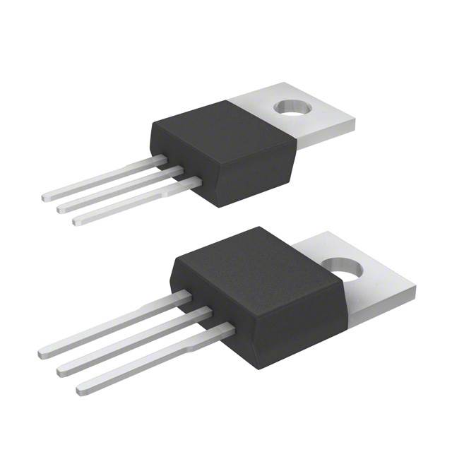
| Package | TO-220-3, Short Tab | TO-247-3 | TO-220-3 Full Pack | TO-220-3 | TO-220-3 |
| Product Status | Obsolete | Active | Active | Active | Active |
| RoHS Status | ROHS3 Compliant | ROHS3 Compliant | ROHS3 Compliant | ROHS3 Compliant | ROHS3 Compliant |
Engineering Selection Recommendations
Direct Substitutes (Full Current Rating Match or Exceeds 20A):
APT22F80B (Microchip Technology) provides the most direct substitution path. This device exceeds the IXFV20N80P current specification at 23A continuous drain current and delivers superior power dissipation capability at 625W. The APT22F80B maintains identical Vdss (800V) and compatible gate voltage specifications (±30V). The primary mechanical difference is the TO-247-3 package, which requires PCB layout modification but offers improved thermal performance through larger lead geometry. Both devices are ROHS3 compliant and active in production, ensuring long-term availability.
STP13N80K5 (STMicroelectronics) qualifies as a direct substitute with 12A continuous drain current. While this rating falls below the IXFV20N80P specification, the device maintains full voltage compatibility (800V Vdss) and gate voltage range (±30V). The STP13N80K5 features significantly lower gate charge (29 nC versus 86 nC), enabling faster switching characteristics. This part is housed in a standard TO-220-3 package, requiring no PCB layout modification. Active product status and ROHS3 compliance confirm production availability.
SPP11N80C3XKSA1 (Infineon Technologies) offers substitution with 11A continuous drain current. This device maintains 800V Vdss and operates within the required temperature range. The SPP11N80C3XKSA1 features reduced input capacitance (1600 pF @ 100V) and lower gate charge (85 nC), supporting improved switching performance. The TO-220-3 package ensures direct mechanical compatibility. Note: Maximum gate voltage is ±20V, which is acceptable for 10V drive voltage applications but limits gate voltage margin compared to the original specification.
Partial Substitutes (Current Rating Below 20A):
R8010ANX (Rohm Semiconductor) is classified as a partial substitute due to 10A continuous drain current, which is 50% below the IXFV20N80P specification. This device maintains 800V Vdss and ±30V gate voltage compatibility. The R8010ANX is suitable only for applications where the actual operating current does not exceed 10A. The TO-220-3 Full Pack configuration provides direct package compatibility. Active product status and ROHS3 compliance are confirmed.
All substitute parts maintain ROHS3 compliance and REACH unaffected status, ensuring regulatory alignment with the original device. Selection should prioritize APT22F80B or STP13N80K5 for applications requiring the full 20A specification, with package form factor and thermal requirements guiding final selection.
Frequently Asked Questions (FAQ)
Q: Can the APT22F80B replace the IXFV20N80P in all applications?
A: The APT22F80B provides electrical substitution with superior current rating (23A versus 20A) and identical voltage specifications (800V Vdss). The primary consideration is the package change from PLUS220 (TO-220-3 Short Tab) to TO-247-3. The TO-247 package has different lead spacing and thermal characteristics. PCB layout modification is required, and thermal management must be re-evaluated due to different lead geometry and mounting surface area. Electrical performance is fully compatible.
Q: Why is the R8010ANX listed as a partial substitute?
A: The R8010ANX has a continuous drain current rating of 10A, which is 50% of the IXFV20N80P specification (20A). This device is suitable only for applications where actual operating current remains at or below 10A. If your application requires the full 20A capability, the R8010ANX will not provide adequate current capacity and may experience thermal stress or failure. Verify actual circuit current requirements before selecting this part.
Q: What is the significance of the SPP11N80C3XKSA1 maximum gate voltage being ±20V instead of ±30V?
A: The IXFV20N80P and most substitute parts accept ±30V maximum gate voltage, providing margin for gate drive circuit variations. The SPP11N80C3XKSA1 limits gate voltage to ±20V. For applications using standard 10V or 15V gate drive circuits, this specification is not restrictive. However, if your gate drive circuit can exceed ±20V, the SPP11N80C3XKSA1 may not be suitable. Verify gate drive voltage specifications before selection.
Q: Are all substitute parts available in the same through-hole mounting configuration?
A: Yes, all listed substitute parts are through-hole mounted devices. However, package form factors differ. The IXFV20N80P uses PLUS220 (TO-220-3 Short Tab), while APT22F80B uses TO-247-3, and the remaining substitutes use standard TO-220-3. The TO-220-3 and TO-247-3 packages have different lead spacing and thermal pad dimensions. PCB layout verification is required when changing package types, particularly for thermal management and lead-to-pad alignment.
Q: Do all substitute parts meet the same compliance requirements as the IXFV20N80P?
A: Yes, all listed substitute parts are ROHS3 compliant and REACH unaffected, matching the original device compliance status. All parts carry EAR99 export classification and identical HTSUS codes (8541.29.0095), confirming regulatory alignment for procurement and supply chain purposes.
Q: Which substitute part offers the best thermal performance?
A: The APT22F80B provides the highest power dissipation rating at 625W, compared to the IXFV20N80P at 500W. The TO-247-3 package also offers larger thermal surface area than PLUS220. However, thermal performance depends on PCB design, heatsink attachment, and airflow conditions. The STP13N80K5 and SPP11N80C3XKSA1 offer lower gate charge (29 nC and 85 nC respectively), which reduces switching losses and heat generation in high-frequency applications.
Q: Can I use multiple lower-current substitute parts in parallel to achieve 20A capability?
A: Parallel operation of MOSFETs requires careful circuit design to ensure current sharing and thermal balance. This approach is not recommended as a standard substitution strategy without detailed analysis of gate drive symmetry, PCB layout, and thermal management. Consult application-specific design guidelines before implementing parallel configurations.
Q: What is the inventory status for substitute parts?
A: APT22F80B: 899 pcs available; R8010ANX: 2600 pcs available; SPP11N80C3XKSA1: 7685 pcs available; STP13N80K5: 4347 pcs available. All parts are listed as new original stock. Verify current availability with your supplier before finalizing procurement decisions.
Alternative Parts

SJ6012L2TP
Littelfuse Inc.
6 Alternative Parts

JMK107BBJ476MA-RE
Taiyo Yuden
10 Alternative Parts

GMK107BBJ475MA-T
Taiyo Yuden
5 Alternative Parts
SJ6020N2ARP
Littelfuse Inc.
3 Alternative Parts
SJ6025R2ATP
Littelfuse Inc.
4 Alternative Parts

2474-05L
API Delevan Inc.
1 Alternative Parts

4590R-684K
API Delevan Inc.
1 Alternative Parts

CM6560R-334
API Delevan Inc.
1 Alternative Parts

CM6460-104
API Delevan Inc.
1 Alternative Parts

5526-12
API Delevan Inc.
1 Alternative Parts