


Request Quote
(Ships tomorrow)
IRLU014NPBF N-Channel MOSFET Equivalent & Substitute Parts
Part Overview
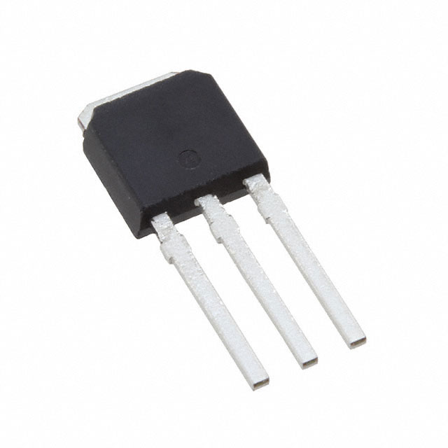
The IRLU014NPBF is an N-Channel MOSFET manufactured by Infineon Technologies, rated for 55V drain-to-source voltage and 10A continuous drain current in a Through Hole IPAK package. This device is classified as Obsolete, necessitating identification of functionally equivalent alternatives for ongoing design support and procurement continuity. The HEXFET® series device operates across a wide temperature range from -55°C to 175°C and dissipates up to 28W at the case temperature.
Substiute Parts
Key Parameters
| Parameter | Value | Unit |
|---|---|---|
| Drain-to-Source Voltage (Vdss) | 55 | V |
| Continuous Drain Current (Id) @ 25°C | 10 | A |
| On-State Resistance (Rds On) @ 6A, 10V | 140 | mOhm |
| Gate Threshold Voltage (Vgs(th)) @ 250µA | 1 | V |
| Gate Charge (Qg) @ 5V | 7.9 | nC |
| Maximum Gate Voltage (Vgs) | ±16 | V |
| Input Capacitance (Ciss) @ 25V | 265 | pF |
| Power Dissipation (Max) | 28 | W |
| Operating Temperature Range | -55 to 175 | °C |
| Package Type | TO-251-3 (IPAK) | Through Hole |
Substitute Part Grouping Explanation
Substitution of the IRLU014NPBF is determined by compatibility across the following critical parameters:
Package and Mounting Compatibility: Both the main part and substitute must use Through Hole mounting in the TO-251-3 (IPAK) package format to ensure direct mechanical and electrical compatibility on existing PCB layouts.
Voltage Rating: The substitute must maintain a Drain-to-Source Voltage (Vdss) rating equal to or greater than 55V to support the same circuit voltage specifications without derating.
Current Handling: The substitute must support continuous drain current (Id) at or above the application requirement. The IRLU014NPBF specifies 10A; substitutes with lower current ratings require circuit re-evaluation.
On-State Resistance (Rds On): Lower Rds On values reduce power dissipation and heat generation. Substitutes with higher Rds On values increase thermal load and may require thermal management adjustments.
Gate Drive Characteristics: Gate threshold voltage (Vgs(th)), gate charge (Qg), and maximum gate voltage (Vgs) must be compatible with existing gate drive circuitry to ensure reliable switching performance.
Temperature Range: The substitute must support the full operating temperature range of -55°C to 175°C or demonstrate compatibility within the application's actual operating envelope.
Compliance and Status: Active product status ensures ongoing availability and support. RoHS and REACH compliance certifications confirm regulatory alignment.
Parameter Comparison
| Parameter | IRLU014NPBF (Main) | STU6NF10 (Substitute) | Compatibility Notes |
|---|---|---|---|
| Manufacturer | Infineon Technologies | STMicroelectronics | Different manufacturers; both established suppliers |
| FET Type | N-Channel | N-Channel | Identical topology |
| Drain-to-Source Voltage (Vdss) | 55 V | 100 V | Substitute rated higher; suitable for 55V applications |
| Continuous Drain Current (Id) @ 25°C | 10 A | 6 A | Substitute rated lower; circuit current must not exceed 6A |
| Rds On (Max) @ Vgs | 140 mOhm @ 6A, 10V | 250 mOhm @ 3A, 10V | Substitute has higher resistance; increased power dissipation |
| Gate Threshold Voltage (Vgs(th)) @ 250µA | 1 V | 4 V | Substitute requires higher gate drive voltage |
| Gate Charge (Qg) @ Vgs | 7.9 nC @ 5V | 14 nC @ 10V | Substitute requires higher gate charge; slower switching |
| Maximum Gate Voltage (Vgs) | ±16 V | ±20 V | Substitute accepts higher gate voltage; compatible |
| Input Capacitance (Ciss) @ 25V | 265 pF | 280 pF | Comparable; minimal impact on gate drive circuit |
| Power Dissipation (Max) | 28 W | 30 W | Similar thermal capability |
| Operating Temperature Range | -55 to 175 °C | -65 to 175 °C | Substitute supports extended low-temperature range |
| Package Type | TO-251-3 (IPAK) | TO-251-3 (IPAK) | Identical package; direct pin compatibility |
| Product Status | Obsolete | Active | Substitute offers long-term availability |
| RoHS Compliance | Not specified | ROHS3 Compliant | Substitute meets current regulatory requirements |
| Moisture Sensitivity (MSL) | 1 (Unlimited) | 1 (Unlimited) | Identical handling requirements |
Engineering Selection Recommendations
Direct Substitution Limitations: The STU6NF10 substitute presents a trade-off scenario rather than a direct equivalent. While package compatibility and voltage rating are suitable, the reduced continuous drain current (6A versus 10A) and increased on-state resistance (250 mOhm versus 140 mOhm) require circuit-level evaluation.
Current Derating: Applications operating at or near the 10A specification of the IRLU014NPBF cannot use the STU6NF10 without circuit modification. The substitute is suitable only for applications with maximum continuous drain current at or below 6A.
Thermal Considerations: The higher Rds On of the STU6NF10 generates increased power dissipation at equivalent current levels. Thermal management design must account for this increase, particularly in high-frequency switching applications.
Gate Drive Compatibility: The STU6NF10 requires a higher gate threshold voltage (4V versus 1V) and higher gate charge (14 nC versus 7.9 nC). Existing gate drive circuits must be verified to deliver sufficient voltage and current to meet these requirements.
Product Status and Compliance: The STU6NF10 is classified as Active with ROHS3 compliance, ensuring long-term procurement availability and regulatory alignment. The IRLU014NPBF Obsolete status justifies transition planning to this substitute for new designs or redesigns.
Recommended Application Scope: The STU6NF10 is suitable as a substitute for IRLU014NPBF applications where continuous drain current does not exceed 6A, gate drive circuitry can accommodate 4V threshold voltage and higher gate charge, and thermal design accounts for increased Rds On dissipation.
Frequently Asked Questions (FAQ)
Q: Can the STU6NF10 directly replace the IRLU014NPBF in all applications?
A: No. While both devices use the TO-251-3 (IPAK) package and share N-Channel MOSFET topology, the STU6NF10 has a lower continuous drain current rating (6A versus 10A) and higher on-state resistance (250 mOhm versus 140 mOhm). Substitution is valid only for applications with maximum continuous drain current at or below 6A and where increased power dissipation is acceptable.
Q: What is the impact of the higher gate threshold voltage in the STU6NF10?
A: The STU6NF10 requires a minimum gate-to-source voltage of 4V to reach threshold, compared to 1V for the IRLU014NPBF. Existing gate drive circuits must be verified to deliver at least 4V to the gate terminal. Low-voltage gate drive circuits may require modification or may not provide adequate drive margin.
Q: Are the packages mechanically identical?
A: Yes. Both devices use the TO-251-3 (IPAK) package with Through Hole mounting. Pin assignments are identical, allowing direct PCB footprint compatibility without layout modification.
Q: How does the higher gate charge affect switching performance?
A: The STU6NF10 requires 14 nC of gate charge at 10V compared to 7.9 nC at 5V for the IRLU014NPBF. Higher gate charge increases switching time and may reduce maximum switching frequency. Gate drive circuits must supply sufficient current to charge the gate within the required switching time window.
Q: Is the STU6NF10 suitable for high-frequency switching applications?
A: The higher gate charge and threshold voltage of the STU6NF10 result in slower switching transitions compared to the IRLU014NPBF. Applications requiring switching frequencies above the original design specification should be re-evaluated with the STU6NF10 characteristics.
Q: What compliance certifications does the STU6NF10 carry?
A: The STU6NF10 is ROHS3 compliant and REACH unaffected. Both devices carry EAR99 ECCN classification and identical HTSUS codes, confirming regulatory and trade compliance alignment.
Q: Can I use the STU6NF10 in a 10A application if I add additional cooling?
A: Thermal management cannot overcome the current rating limitation. The STU6NF10 is rated for a maximum continuous drain current of 6A at 25°C case temperature. Operating above this rating violates the device specification regardless of cooling measures and voids reliability guarantees.
Q: What is the temperature range difference between these devices?
A: The IRLU014NPBF operates from -55°C to 175°C, while the STU6NF10 extends the low-temperature range to -65°C. Both support the same maximum junction temperature of 175°C. The STU6NF10 is suitable for applications requiring extended low-temperature operation.
Alternative Parts

SJ6012L2TP
Littelfuse Inc.
6 Alternative Parts

JMK107BBJ476MA-RE
Taiyo Yuden
10 Alternative Parts

GMK107BBJ475MA-T
Taiyo Yuden
5 Alternative Parts
SJ6020N2ARP
Littelfuse Inc.
3 Alternative Parts
SJ6025R2ATP
Littelfuse Inc.
4 Alternative Parts

2474-05L
API Delevan Inc.
1 Alternative Parts

4590R-684K
API Delevan Inc.
1 Alternative Parts

CM6560R-334
API Delevan Inc.
1 Alternative Parts

CM6460-104
API Delevan Inc.
1 Alternative Parts

5526-12
API Delevan Inc.
1 Alternative Parts