


Request Quote
(Ships tomorrow)
IRG4PC40UD-EPBF IGBT Equivalent & Substitute Parts
Part Overview
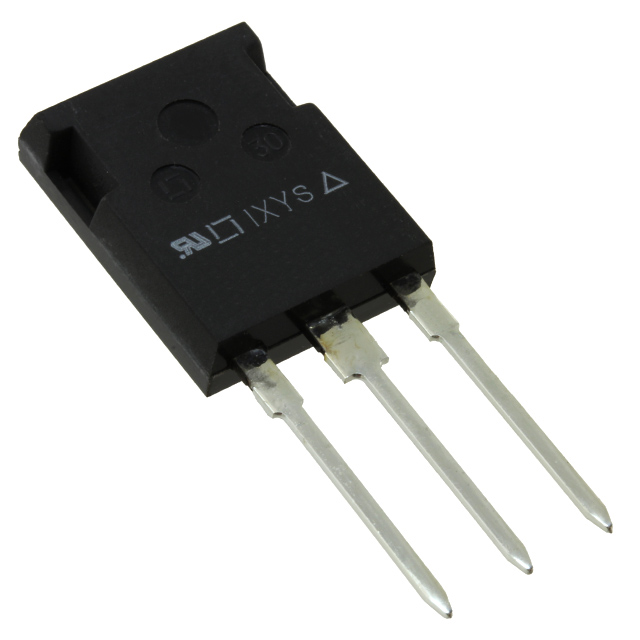
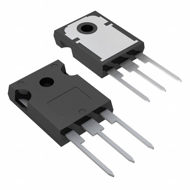
The IRG4PC40UD-EPBF is a 600V, 40A IGBT manufactured by Infineon Technologies in TO-247-3 package configuration. This device is classified as obsolete product status, necessitating identification of active equivalent and substitute components for ongoing design requirements and procurement needs. The part operates across a junction temperature range of -55°C to 150°C with maximum power dissipation of 160W and is fully RoHS3 compliant.
Substiute Parts
Key Parameters
| Parameter | Value | Unit |
|---|---|---|
| Voltage - Collector Emitter Breakdown (Max) | 600 | V |
| Current - Collector (Ic) (Max) | 40 | A |
| Current - Collector Pulsed (Icm) | 160 | A |
| Vce(on) (Max) @ Vge, Ic | 2.1V @ 15V, 20A | V |
| Power - Max | 160 | W |
| Switching Energy (on/off) | 710µJ / 350µJ | µJ |
| Gate Charge | 100 | nC |
| Td (on/off) @ 25°C | 54ns / 110ns | ns |
| Reverse Recovery Time (trr) | 42 | ns |
| Operating Temperature (TJ) | -55°C to 150°C | °C |
| Package / Case | TO-247-3 | - |
| Mounting Type | Through Hole | - |
| RoHS Status | ROHS3 Compliant | - |
Substitute Part Grouping Explanation
Substitution eligibility for the IRG4PC40UD-EPBF is determined by strict alignment of the following critical electrical and mechanical parameters:
Primary Substitution Criteria:
- Voltage - Collector Emitter Breakdown (Max): 600V minimum
- Current - Collector (Ic) (Max): 40A minimum
- Package / Case: TO-247-3 or equivalent through-hole configuration
- Mounting Type: Through Hole
- RoHS Status: ROHS3 Compliant
Secondary Compatibility Parameters:
- Vce(on) characteristics within acceptable operating range
- Gate Charge and switching delay times suitable for existing gate drive circuits
- Operating temperature range compatibility with application requirements
The substitute parts identified below meet these criteria and are classified as active products, ensuring long-term availability and supply chain continuity.
Parameter Comparison
| Parameter | IRG4PC40UD-EPBF | IKW20N60H3FKSA1 | IKW20N60TFKSA1 | IXDR35N60BD1 | STGW20V60DF | STGW40H60DLFB |
|---|---|---|---|---|---|---|
| Manufacturer | Infineon | Infineon | Infineon | IXYS | STMicroelectronics | STMicroelectronics |
| Voltage - Collector Emitter Breakdown (Max) | 600V | 600V | 600V | 600V | 600V | 600V |
| Current - Collector (Ic) (Max) | 40A | 40A | 40A | 38A | 40A | 80A |
| Current - Collector Pulsed (Icm) | 160A | 80A | 60A | 48A | 80A | 160A |
| Vce(on) (Max) @ Vge, Ic | 2.1V @ 15V, 20A | 2.4V @ 15V, 20A | 2.05V @ 15V, 20A | 2.7V @ 15V, 35A | 2.2V @ 15V, 20A | 2V @ 15V, 40A |
| Power - Max | 160W | 170W | 166W | 125W | 167W | 283W |
| Gate Charge | 100nC | 120nC | 120nC | 140nC | 116nC | 210nC |
| Td (on/off) @ 25°C | 54ns / 110ns | 17ns / 194ns | 18ns / 199ns | - / - | 38ns / 149ns | - / 142ns |
| Reverse Recovery Time (trr) | 42ns | 112ns | 41ns | 40ns | 40ns | - |
| Operating Temperature (TJ) | -55°C to 150°C | -40°C to 175°C | - | -55°C to 150°C | -55°C to 175°C | -55°C to 175°C |
| Package / Case | TO-247-3 | TO-247-3 | TO-247-3 | TO-247-3 | TO-247-3 | TO-247-3 |
| Product Status | Obsolete | Active | Active | Active | Active | Active |
| RoHS Status | ROHS3 Compliant | ROHS3 Compliant | ROHS3 Compliant | ROHS3 Compliant | ROHS3 Compliant | ROHS3 Compliant |
Engineering Selection Recommendations
Primary Substitutes (Direct Equivalents):
IKW20N60TFKSA1 and STGW20V60DF are the preferred direct substitutes for the IRG4PC40UD-EPBF. Both devices maintain identical voltage and current ratings (600V, 40A), operate in the same TO-247-3 package, and are classified as active products with full RoHS3 compliance. IKW20N60TFKSA1 offers superior Vce(on) performance at 2.05V compared to the original 2.1V specification, while STGW20V60DF provides enhanced switching energy efficiency with 200µJ on-state and 130µJ off-state switching energy.
Secondary Substitutes (Functional Equivalents):
IKW20N60H3FKSA1 meets all primary substitution criteria with 600V, 40A ratings and TO-247-3 packaging. This device features TrenchStop® technology and extended operating temperature range to 175°C. Higher gate charge (120nC versus 100nC) and increased reverse recovery time (112ns versus 42ns) require gate drive circuit evaluation for compatibility.
STGW40H60DLFB provides higher current capability (80A) with superior power dissipation (283W) in the same TO-247-3 package. This device is suitable for applications requiring increased current headroom or thermal margin. Higher gate charge (210nC) necessitates gate drive circuit assessment.
Conditional Substitute:
IXDR35N60BD1 operates at slightly reduced current rating (38A versus 40A) and lower maximum power (125W versus 160W). This device is suitable only for applications with current requirements below 38A. Higher Vce(on) (2.7V @ 15V, 35A) and gate charge (140nC) require thermal and drive circuit verification.
Compliance and Availability:
All identified substitutes maintain ROHS3 compliance and REACH unaffected status, matching the original device specifications. All substitute parts are classified as active products with confirmed inventory availability, ensuring supply chain continuity.
Frequently Asked Questions (FAQ)
Q1: Can IKW20N60H3FKSA1 directly replace IRG4PC40UD-EPBF without circuit modifications?
A: IKW20N60H3FKSA1 meets the primary electrical and mechanical substitution criteria (600V, 40A, TO-247-3 package). However, the increased gate charge (120nC versus 100nC) and reverse recovery time (112ns versus 42ns) may require gate drive circuit evaluation. Switching delay characteristics differ significantly (17ns on-time versus 54ns), necessitating timing analysis for applications with strict switching frequency requirements.
Q2: What is the difference between Trench Field Stop and NPT IGBT technology in these substitutes?
A: The substitute parts employ different IGBT architectures. Trench Field Stop devices (IKW20N60H3FKSA1, IKW20N60TFKSA1, STGW20V60DF, STGW40H60DLFB) offer improved switching performance and lower switching losses. NPT technology (IXDR35N60BD1) provides different trade-offs in conduction and switching characteristics. Selection depends on application-specific requirements for switching frequency, thermal management, and efficiency targets.
Q3: Is STGW40H60DLFB suitable as a substitute despite its 80A current rating?
A: STGW40H60DLFB is functionally compatible for applications operating at or below 40A continuous current. The higher current rating (80A) provides additional design margin and thermal headroom. However, the significantly higher gate charge (210nC) requires gate drive circuit verification to ensure adequate drive capability and switching performance. This device is recommended only when increased current capacity or thermal margin is beneficial to the application.
Q4: What are the package compatibility considerations for these substitutes?
A: All identified substitutes utilize TO-247-3 through-hole packaging, maintaining mechanical and thermal interface compatibility with the original IRG4PC40UD-EPBF. Pin configurations are identical, allowing direct PCB mounting without layout modifications. Thermal performance depends on heatsink interface and mounting pressure consistency across all devices.
Q5: How do switching energy characteristics affect device selection?
A: Switching energy directly impacts power dissipation and thermal management requirements. STGW20V60DF exhibits the lowest switching energy (200µJ on, 130µJ off), reducing thermal load in high-frequency applications. IKW20N60H3FKSA1 shows higher switching energy (800µJ), requiring enhanced thermal design. Application switching frequency and thermal budget determine the optimal device selection.
Q6: Are there operating temperature range limitations for substitution?
A: The original IRG4PC40UD-EPBF operates from -55°C to 150°C. Most substitutes extend the upper temperature limit to 175°C (IKW20N60H3FKSA1, STGW20V60DF, STGW40H60DLFB), providing enhanced thermal margin. IKW20N60TFKSA1 operating temperature range is not specified in available data. Applications requiring operation above 150°C benefit from substitutes with extended temperature ratings.
Alternative Parts

SJ6012L2TP
Littelfuse Inc.
6 Alternative Parts

JMK107BBJ476MA-RE
Taiyo Yuden
10 Alternative Parts

GMK107BBJ475MA-T
Taiyo Yuden
5 Alternative Parts
SJ6020N2ARP
Littelfuse Inc.
3 Alternative Parts
SJ6025R2ATP
Littelfuse Inc.
4 Alternative Parts

2474-05L
API Delevan Inc.
1 Alternative Parts

4590R-684K
API Delevan Inc.
1 Alternative Parts

CM6560R-334
API Delevan Inc.
1 Alternative Parts

CM6460-104
API Delevan Inc.
1 Alternative Parts

5526-12
API Delevan Inc.
1 Alternative Parts