


Request Quote
(Ships tomorrow)
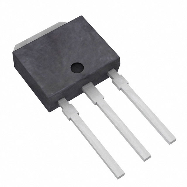
IRFU120ZPBF N-Channel MOSFET 100V 8.7A Equivalent & Substitute Parts
Part Overview
The IRFU120ZPBF is an N-Channel MOSFET manufactured by Infineon Technologies, rated for 100V drain-to-source voltage with 8.7A continuous drain current at 25°C. The device is housed in an IPAK (TO-251AA) through-hole package and is designed for general-purpose switching applications requiring moderate current handling and thermal performance up to 35W.
The IRFU120ZPBF is classified as obsolete. Equivalent and substitute parts are necessary to maintain design continuity and ensure component availability for new production runs, repairs, and system upgrades. Substitute devices must maintain electrical compatibility across voltage ratings, current specifications, and thermal characteristics while accommodating the same or compatible package footprints.
Substiute Parts
Key Parameters
| Parameter | Value | Unit |
|---|---|---|
| Drain-to-Source Voltage (Vdss) | 100 | V |
| Continuous Drain Current (Id) @ 25°C | 8.7 | A (Tc) |
| On-State Resistance (Rds On Max) @ Id, Vgs | 190 mOhm @ 5.2A, 10V | mOhm |
| Gate Threshold Voltage (Vgs(th) Max) @ Id | 4 | V @ 250µA |
| Gate Charge (Qg Max) @ Vgs | 10 | nC @ 10V |
| Power Dissipation (Max) | 35 | W (Tc) |
| Operating Temperature Range | -55 to 175 | °C (TJ) |
| Package Type | TO-251-3 (IPAK) | Through Hole |
| Moisture Sensitivity Level | 1 | Unlimited |
Substitute Part Grouping Explanation
Substitution eligibility for the IRFU120ZPBF is determined by the following critical parameters:
Voltage Rating Compatibility: All substitute parts must maintain a Vdss rating of 100V or greater to ensure safe operation within the original design envelope.
Current Rating Compatibility: Substitute parts must support continuous drain current (Id) at or above 8.7A at 25°C to meet or exceed the original device performance.
On-State Resistance (Rds On): The maximum on-state resistance must not significantly exceed the original specification to prevent excessive power dissipation and thermal stress in the circuit.
Package and Mounting: All substitutes must use the TO-251-3 (IPAK) through-hole package to ensure direct mechanical and electrical compatibility with existing PCB layouts.
Gate Threshold Voltage (Vgs(th)): Gate drive requirements must remain within ±20V maximum gate voltage specification to ensure compatibility with existing gate drive circuits.
Thermal Performance: Power dissipation capability must support the thermal requirements of the application without exceeding the original 35W specification or requiring additional thermal management modifications.
Operating Temperature Range: The substitute must support the full operating temperature range of -55°C to 175°C (TJ) or demonstrate compatibility within the application's actual operating window.
Parameter Comparison
| Parameter | IRFU120ZPBF (Main) | IRFU120NPBF | IRFU120PBF | STU6NF10 |
|---|---|---|---|---|
| Manufacturer | Infineon Technologies | Infineon Technologies | Vishay Siliconix | STMicroelectronics |
| Drain-to-Source Voltage (Vdss) | 100 V | 100 V | 100 V | 100 V |
| Continuous Drain Current (Id) @ 25°C | 8.7 A (Tc) | 9.4 A (Tc) | 7.7 A (Tc) | 6 A (Tc) |
| Rds On (Max) @ Id, Vgs | 190 mOhm @ 5.2A, 10V | 210 mOhm @ 5.6A, 10V | 270 mOhm @ 4.6A, 10V | 250 mOhm @ 3A, 10V |
| Gate Threshold Voltage (Vgs(th) Max) @ Id | 4 V @ 250µA | 4 V @ 250µA | 4 V @ 250µA | 4 V @ 250µA |
| Gate Charge (Qg Max) @ Vgs | 10 nC @ 10V | 25 nC @ 10V | 16 nC @ 10V | 14 nC @ 10V |
| Input Capacitance (Ciss Max) @ Vds | 310 pF @ 25V | 330 pF @ 25V | 360 pF @ 25V | 280 pF @ 25V |
| Power Dissipation (Max) | 35 W (Tc) | 48 W (Tc) | 42 W (Tc) | 30 W (Tc) |
| Operating Temperature Range | -55 to 175 °C (TJ) | -55 to 175 °C (TJ) | -55 to 150 °C (TJ) | -65 to 175 °C (TJ) |
| Package Type | TO-251-3 (IPAK) | TO-251-3 (IPAK) | TO-251-3 (IPAK) | TO-251 (IPAK) |
| Product Status | Obsolete | Active | Active | Active |
| RoHS Status | Not specified | ROHS3 Compliant | ROHS3 Compliant | ROHS3 Compliant |
Engineering Selection Recommendations
IRFU120NPBF (Infineon Technologies): This part is the primary recommended substitute. It maintains the same manufacturer (Infineon Technologies HEXFET® series), identical voltage rating (100V), and exceeds the original current specification (9.4A vs. 8.7A). The device is in active production status with ROHS3 compliance. Higher power dissipation capability (48W vs. 35W) provides thermal margin. Gate charge is elevated (25 nC vs. 10 nC), requiring verification of gate drive circuit compatibility. Operating temperature range matches the original specification (-55°C to 175°C). Packaging is identical TO-251-3 (IPAK). Inventory availability is substantial (110,300 pcs).
IRFU120PBF (Vishay Siliconix): This substitute is electrically compatible with the original device, maintaining 100V voltage rating and supporting 7.7A continuous current. The part is in active production with ROHS3 compliance. On-state resistance is higher (270 mOhm vs. 190 mOhm), resulting in increased power dissipation per ampere. Operating temperature range is reduced to -55°C to 150°C, which may limit suitability for applications requiring full -55°C to 175°C operation. Package type is identical TO-251-3 (IPAK). Inventory availability is adequate (15,165 pcs).
STU6NF10 (STMicroelectronics): This substitute provides 100V voltage rating and operates within the same package footprint (TO-251 IPAK). Continuous drain current is reduced to 6A, which falls below the original 8.7A specification. This device is suitable only for applications where the actual current requirement is 6A or less. On-state resistance is elevated (250 mOhm vs. 190 mOhm). The part is in active production with ROHS3 compliance and supports the full operating temperature range (-65°C to 175°C). Gate charge is lower (14 nC vs. 10 nC), potentially offering faster switching characteristics. Inventory availability is adequate (15,426 pcs).
Selection Criteria: For direct replacement in applications requiring 8.7A or greater continuous current, IRFU120NPBF is the primary choice. For applications with reduced current requirements (below 8.7A), IRFU120PBF or STU6NF10 may be considered with thermal and gate drive circuit verification. All three substitutes are in active production and ROHS3 compliant, ensuring long-term availability and regulatory compliance.
Frequently Asked Questions (FAQ)
Q: Can IRFU120NPBF directly replace IRFU120ZPBF without circuit modifications?
A: IRFU120NPBF maintains electrical compatibility across voltage rating (100V), gate threshold voltage (4V @ 250µA), and package type (TO-251-3 IPAK). The higher gate charge (25 nC vs. 10 nC) may require verification of gate drive circuit current capacity to ensure adequate switching speed. No PCB layout modifications are required due to identical package footprint.
Q: What is the impact of higher on-state resistance in substitute parts?
A: On-state resistance directly affects power dissipation according to P = I²Rds. IRFU120PBF (270 mOhm) dissipates approximately 42% more power than IRFU120ZPBF (190 mOhm) at 8.7A. This may require thermal management review, including heatsink sizing and PCB copper area allocation. IRFU120NPBF (210 mOhm) presents a 10.5% increase, which is typically acceptable within thermal design margins.
Q: Is STU6NF10 suitable for all IRFU120ZPBF applications?
A: STU6NF10 is suitable only for applications where continuous drain current does not exceed 6A. The 100V voltage rating and TO-251 package are compatible, but the reduced current specification makes this device unsuitable for designs requiring the full 8.7A capability of the original part.
Q: What are the gate drive circuit implications of different gate charge specifications?
A: Gate charge (Qg) determines the total charge required to switch the device. IRFU120NPBF (25 nC) requires 2.5 times more charge than IRFU120ZPBF (10 nC), potentially increasing switching time and gate drive power dissipation. Gate drive circuits with current-limited outputs may experience slower switching transitions. Verification of gate drive circuit specifications is required before substitution.
Q: Are all substitute parts ROHS3 compliant?
A: Yes. IRFU120NPBF, IRFU120PBF, and STU6NF10 are all ROHS3 compliant. The original IRFU120ZPBF compliance status is not specified in the provided data. All substitutes meet current environmental and regulatory requirements for new production.
Q: What is the significance of operating temperature range differences?
A: IRFU120PBF operates to 150°C (TJ) maximum, compared to 175°C for the original and other substitutes. Applications requiring operation above 150°C junction temperature must use IRFU120NPBF or STU6NF10. STU6NF10 extends the lower temperature limit to -65°C, providing additional margin for extreme cold-weather applications.
Q: Can these parts be used interchangeably in existing inventory?
A: Direct interchangeability is limited to IRFU120NPBF for applications requiring full 8.7A current capability. IRFU120PBF and STU6NF10 require application-specific current verification. All three parts use identical TO-251-3 (IPAK) package footprints, enabling mechanical interchangeability on PCBs. Electrical verification of gate drive circuits and thermal performance is required before field substitution.
Alternative Parts

SJ6012L2TP
Littelfuse Inc.
6 Alternative Parts

JMK107BBJ476MA-RE
Taiyo Yuden
10 Alternative Parts

GMK107BBJ475MA-T
Taiyo Yuden
5 Alternative Parts
SJ6020N2ARP
Littelfuse Inc.
3 Alternative Parts
SJ6025R2ATP
Littelfuse Inc.
4 Alternative Parts

2474-05L
API Delevan Inc.
1 Alternative Parts

4590R-684K
API Delevan Inc.
1 Alternative Parts

CM6560R-334
API Delevan Inc.
1 Alternative Parts

CM6460-104
API Delevan Inc.
1 Alternative Parts

5526-12
API Delevan Inc.
1 Alternative Parts