


Request Quote
(Ships tomorrow)
IRFIB7N50LPBF N-Channel 500V 6.8A MOSFET Equivalent & Substitute Parts
Part Overview
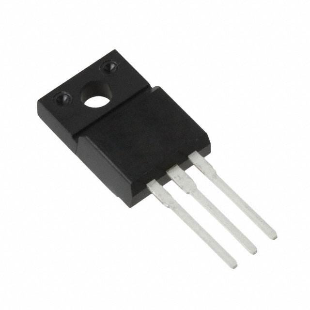
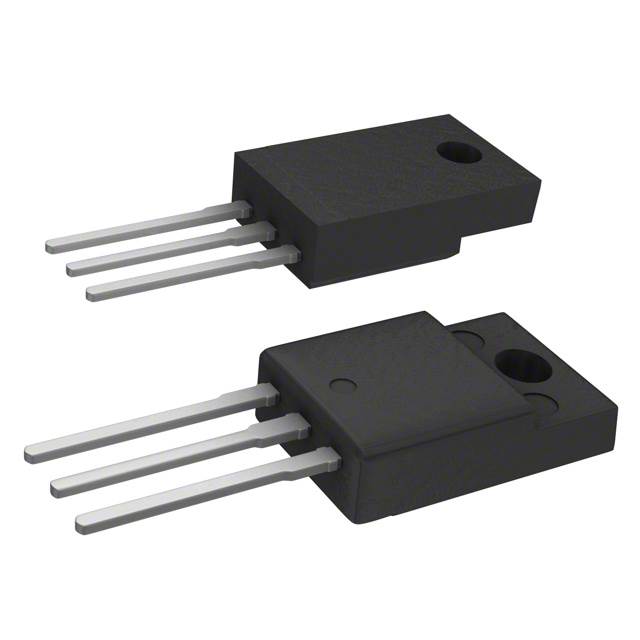
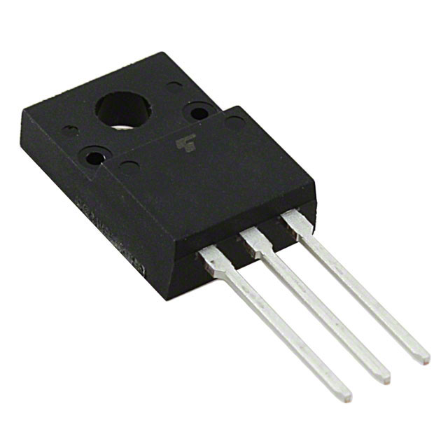
The IRFIB7N50LPBF is an N-Channel metal oxide semiconductor field-effect transistor (MOSFET) manufactured by Vishay Siliconix, rated for 500V drain-to-source voltage and 6.8A continuous drain current. The device is packaged in a TO-220-3 through-hole configuration and is rated for 46W power dissipation. This part is classified as obsolete, making identification of functionally equivalent substitute components necessary for ongoing design support, maintenance, and production continuity.
Substiute Parts
Key Parameters
| Parameter | Value | Unit |
|---|---|---|
| Manufacturer Part Number | IRFIB7N50LPBF | — |
| Manufacturer | Vishay Siliconix | — |
| FET Type | N-Channel | — |
| Technology | MOSFET (Metal Oxide) | — |
| Drain to Source Voltage (Vdss) | 500 | V |
| Current - Continuous Drain (Id) @ 25°C | 6.8 | A (Tc) |
| Rds On (Max) @ Id, Vgs | 380 | mOhm @ 4.1A, 10V |
| Gate Charge (Qg) (Max) @ Vgs | 92 | nC @ 10V |
| Vgs (Max) | ±30 | V |
| Power Dissipation (Max) | 46 | W (Tc) |
| Operating Temperature | -55 to 150 | °C (TJ) |
| Mounting Type | Through Hole | — |
| Package / Case | TO-220-3 Full Pack, Isolated Tab | — |
| Product Status | Obsolete | — |
| RoHS Status | ROHS3 Compliant | — |
Substitute Part Grouping Explanation
Substitution of the IRFIB7N50LPBF is determined by strict alignment of the following electrical and mechanical parameters:
Critical Matching Parameters:
- Drain to Source Voltage (Vdss): 500V minimum
- FET Type: N-Channel
- Technology: MOSFET (Metal Oxide)
- Mounting Type: Through Hole
- Package / Case: TO-220-3 compatible form factor
Performance Parameters (Allowable Ranges):
- Continuous Drain Current (Id): Equal to or greater than 6.8A
- Rds On (Max): Equal to or less than 380 mOhm (lower is acceptable)
- Gate Charge (Qg): Lower values are acceptable
- Power Dissipation: Equal to or greater than 46W
- Operating Temperature Range: Must include -55°C to 150°C or equivalent
Compliance Requirements:
- RoHS3 Compliant
- REACH Unaffected status
- Moisture Sensitivity Level (MSL): 1 (Unlimited)
Substitute parts listed below meet all critical matching parameters and maintain electrical performance within acceptable engineering tolerances for direct replacement applications.
Parameter Comparison
| Parameter | IRFIB7N50LPBF | IPA50R350CPXKSA1 | R5016FNX | STF11NM50N | STF14NM50N | STP11NK50ZFP | STP12NM50FP | STP14NK50ZFP | TK13A50D | TK14A55D | TK15A50D |
|---|---|---|---|---|---|---|---|---|---|---|---|
| Manufacturer | Vishay Siliconix | Infineon | Rohm | STMicroelectronics | STMicroelectronics | STMicroelectronics | STMicroelectronics | STMicroelectronics | Toshiba | Toshiba | Toshiba |
| Vdss (V) | 500 | 500 | 500 | 500 | 500 | 500 | 500 | 500 | 500 | 550 | 500 |
| Id @ 25°C (A) | 6.8 | 10 | 16 | 8.5 | 12 | 10 | 12 | 14 | 13 | 14 | 15 |
| Rds On (Max) (mOhm) | 380 | 350 | 325 | 470 | 320 | 520 | 350 | 380 | 400 | 370 | 300 |
| Qg (Max) (nC) | 92 | 25 | 46 | 19 | 27 | 68 | 39 | 92 | 38 | 40 | 40 |
| Vgs (Max) (V) | ±30 | ±20 | ±30 | ±25 | ±25 | ±30 | ±30 | ±30 | ±30 | ±30 | ±30 |
| Power Dissipation (W) | 46 | 32 | 50 | 25 | 25 | 30 | 35 | 35 | 45 | 50 | 50 |
| Operating Temp (°C) | -55 to 150 | -55 to 150 | 150 | 150 | -55 to 150 | -55 to 150 | -65 to 150 | -55 to 150 | 150 | 150 | 150 |
| Package | TO-220-3 | PG-TO220-3-31 | TO-220FM | TO-220FP | TO-220FP | TO-220FP | TO-220FP | TO-220FP | TO-220SIS | TO-220SIS | TO-220SIS |
| Product Status | Obsolete | Last Time Buy | Active | Active | Active | Not For New Designs | Active | Active | Active | Active | Active |
| RoHS Status | ROHS3 Compliant | ROHS3 Compliant | ROHS3 Compliant | ROHS3 Compliant | ROHS3 Compliant | ROHS3 Compliant | ROHS3 Compliant | ROHS3 Compliant | ROHS3 Compliant | ROHS3 Compliant | ROHS3 Compliant |
Engineering Selection Recommendations
Primary Substitutes (Active Product Status):
The following parts are recommended as primary substitutes due to active product status and full compliance with RoHS3 and REACH requirements:
R5016FNX (Rohm Semiconductor) — Active status. Provides 16A continuous drain current with 325 mOhm Rds On, exceeding the IRFIB7N50LPBF performance envelope. 50W power dissipation rating. TO-220FM package compatible with TO-220-3 mounting requirements. Suitable for applications requiring higher current capacity.
STF14NM50N (STMicroelectronics) — Active status. Delivers 12A continuous drain current with 320 mOhm Rds On and 25W power dissipation. MDmesh™ II series technology. Operating temperature range -55°C to 150°C matches original specification. TO-220FP package form factor.
STP12NM50FP (STMicroelectronics) — Active status. Rated for 12A continuous drain current with 350 mOhm Rds On and 35W power dissipation. MDmesh™ series. Extended operating temperature range -65°C to 150°C. TO-220FP package.
STP14NK50ZFP (STMicroelectronics) — Active status. Provides 14A continuous drain current with 380 mOhm Rds On (matching original specification) and 35W power dissipation. SuperMESH™ series. Operating temperature -55°C to 150°C. TO-220FP package.
TK13A50D(STA4,Q,M) (Toshiba Semiconductor) — Active status. Rated for 13A continuous drain current with 400 mOhm Rds On and 45W power dissipation. π-MOSVII series. TO-220SIS package. Vgs (Max) ±30V matches original.
TK14A55D(STA4,Q,M) (Toshiba Semiconductor) — Active status. Delivers 14A continuous drain current with 370 mOhm Rds On and 50W power dissipation. π-MOSVII series. Vdss rated at 550V (exceeds 500V requirement). TO-220SIS package.
TK15A50D(STA4,Q,M) (Toshiba Semiconductor) — Active status. Provides 15A continuous drain current with 300 mOhm Rds On and 50W power dissipation. π-MOSVII series. TO-220SIS package. Superior Rds On performance.
Secondary Substitutes (Limited Availability or Restricted Status):
IPA50R350CPXKSA1 (Infineon Technologies) — Last Time Buy status. CoolMOS™ series. 10A continuous drain current with 350 mOhm Rds On and 32W power dissipation. Operating temperature -55°C to 150°C. PG-TO220-3-31 package (TO-220-3 compatible). Suitable for applications with extended lead time planning.
STF11NM50N (STMicroelectronics) — Active status. MDmesh™ II series. 8.5A continuous drain current with 470 mOhm Rds On and 25W power dissipation. Lower current rating than original; suitable only for reduced-current applications.
STP11NK50ZFP (STMicroelectronics) — Not For New Designs status. SuperMESH™ series. 10A continuous drain current with 520 mOhm Rds On and 30W power dissipation. Restricted for new design implementations; suitable for legacy system maintenance only.
Frequently Asked Questions (FAQ)
Q: Can I use a substitute part with higher drain current rating than the IRFIB7N50LPBF?
A: Yes. Substitute parts with equal or greater continuous drain current (Id) ratings are electrically compatible. Higher current ratings indicate enhanced performance capability and do not compromise circuit operation when the original design current requirement is 6.8A or less.
Q: What is the significance of Rds On (on-resistance) in substitution?
A: Rds On determines power dissipation and heat generation during operation. Substitute parts with equal or lower Rds On values are acceptable. Lower Rds On reduces power loss and improves efficiency. The IRFIB7N50LPBF specifies 380 mOhm maximum; substitutes with 380 mOhm or lower are directly compatible.
Q: Are TO-220FP, TO-220FM, and TO-220SIS packages interchangeable with TO-220-3?
A: All listed variants (TO-220FP, TO-220FM, TO-220SIS) are through-hole TO-220-3 compatible form factors. Physical mounting and pin configuration are compatible with standard TO-220-3 PCB layouts. Verify specific package dimensions if space constraints exist.
Q: Why is the IRFIB7N50LPBF classified as obsolete?
A: Obsolete status indicates the manufacturer has discontinued production. Substitute parts listed are active or last-time-buy status, ensuring continued availability for replacement and maintenance applications.
Q: What does "Not For New Designs" status mean for STP11NK50ZFP?
A: This designation indicates the manufacturer restricts the part for new design implementations but continues to support existing applications. STP11NK50ZFP is suitable for legacy system maintenance and repair but should not be selected for new product development.
Q: How do I verify that a substitute part is compatible with my circuit?
A: Confirm that the substitute meets or exceeds the following parameters: Vdss ≥ 500V, Id ≥ 6.8A, Rds On ≤ 380 mOhm, Vgs (Max) ≥ ±30V, and operating temperature range includes -55°C to 150°C. All listed substitutes satisfy these criteria.
Q: Are all substitute parts RoHS3 compliant?
A: Yes. All substitute parts listed in this reference are RoHS3 compliant and REACH unaffected, meeting current environmental and regulatory requirements.
Q: What is the difference between Tc and Ta temperature ratings?
A: Tc (case temperature) and Ta (ambient temperature) are different measurement points. Tc is measured at the device case; Ta is measured in the surrounding environment. Both are provided in the parameter comparison table. Verify your application's thermal management requirements against the appropriate specification.
Q: Can I use TK14A55D with 550V Vdss rating in a 500V circuit?
A: Yes. The TK14A55D is rated for 550V Vdss, which exceeds the 500V requirement of the original circuit. Higher voltage ratings provide additional safety margin and are fully compatible with 500V applications.
Q: What is Gate Charge (Qg) and why does it matter for substitution?
A: Gate Charge represents the total charge required to switch the MOSFET on or off. Lower Qg values reduce switching losses and improve efficiency. Substitute parts with lower Qg are acceptable and often provide performance improvements. The IRFIB7N50LPBF specifies 92 nC; substitutes with lower values (such as STF11NM50N at 19 nC) reduce switching energy.
Alternative Parts

SJ6012L2TP
Littelfuse Inc.
6 Alternative Parts

JMK107BBJ476MA-RE
Taiyo Yuden
10 Alternative Parts

GMK107BBJ475MA-T
Taiyo Yuden
5 Alternative Parts
SJ6020N2ARP
Littelfuse Inc.
3 Alternative Parts
SJ6025R2ATP
Littelfuse Inc.
4 Alternative Parts

2474-05L
API Delevan Inc.
1 Alternative Parts

4590R-684K
API Delevan Inc.
1 Alternative Parts

CM6560R-334
API Delevan Inc.
1 Alternative Parts

CM6460-104
API Delevan Inc.
1 Alternative Parts

5526-12
API Delevan Inc.
1 Alternative Parts