


Request Quote
(Ships tomorrow)
IPW65R041CFDFKSA1 Equivalent & Substitute Parts
Part Overview
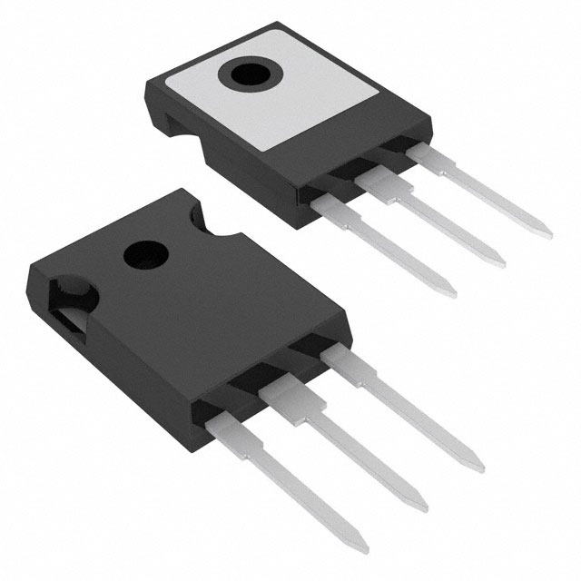
The IPW65R041CFDFKSA1 is an N-Channel 650V 68.5A MOSFET manufactured by Infineon Technologies in the CoolMOS™ series, housed in a TO-247-3 through-hole package. This device is classified as obsolete, necessitating identification of active equivalent and substitute components for new designs and production continuity. The part delivers 500W maximum power dissipation and operates across a temperature range of -55°C to 150°C (TJ).
Substiute Parts
Key Parameters
| Parameter | Value | Unit |
|---|---|---|
| Drain to Source Voltage (Vdss) | 650 | V |
| Continuous Drain Current (Id) @ 25°C | 68.5 | A (Tc) |
| On-State Resistance (Rds On Max) @ 33.1A, 10V | 41 | mOhm |
| Gate Threshold Voltage (Vgs(th) Max) @ 3.3mA | 4.5 | V |
| Gate Charge (Qg Max) @ 10V | 300 | nC |
| Input Capacitance (Ciss Max) @ 100V | 8400 | pF |
| Power Dissipation (Max) | 500 | W (Tc) |
| Operating Temperature Range | -55 to 150 | °C (TJ) |
| Package Type | TO-247-3 | Through Hole |
| RoHS Status | ROHS3 Compliant |
Substitute Part Grouping Explanation
Substitution eligibility for the IPW65R041CFDFKSA1 is determined by the following critical parameters:
Primary Matching Criteria:
- Drain to Source Voltage (Vdss): 600V minimum to 650V maximum
- Continuous Drain Current (Id): 58A minimum to 69A
- On-State Resistance (Rds On): 32mOhm to 45mOhm @ 10V gate drive
- Package Type: TO-247-3 through-hole configuration
- Operating Temperature: -55°C to 150°C minimum range
Secondary Compatibility Factors:
- Gate Threshold Voltage (Vgs(th)): 3.5V to 5V
- Gate Charge (Qg): 121nC to 410nC @ 10V
- Input Capacitance (Ciss): 5348pF to 9800pF @ 100V
- Power Dissipation: 330W minimum
Substitutes are grouped into two categories: parametric equivalents (identical electrical specifications) and manufacturer-recommended alternatives (functionally compatible with minor parameter variations within application tolerances).
Parameter Comparison
| Part Number | Manufacturer | Vdss (V) | Id @ 25°C (A) | Rds On Max (mOhm) | Qg Max (nC) | Ciss Max (pF) | Pd Max (W) | Status |
|---|---|---|---|---|---|---|---|---|
| IPW65R041CFDFKSA1 | Infineon | 650 | 68.5 | 41 | 300 | 8400 | 500 | Obsolete |
| IPW65R041CFDFKSA2 | Infineon | 650 | 68.5 | 41 | 300 | 8400 | 500 | Active |
| STW77N65M5 | STMicroelectronics | 650 | 69 | 38 | 200 | 9800 | 400 | Active |
| STW78N65M5 | STMicroelectronics | 650 | 69 | 32 | 203 | 9000 | 450 | Active |
| STW69N65M5 | STMicroelectronics | 650 | 58 | 45 | 143 | 6420 | 330 | Active |
| STW72N60DM2AG | STMicroelectronics | 600 | 66 | 42 | 121 | 5508 | 446 | Active |
| SIHG70N60AEF-GE3 | Vishay Siliconix | 600 | 60 | 41 | 410 | 5348 | 417 | Active |
| TK62N60X,S1F | Toshiba | 600 | 61.8 | 40 | 135 | 6500 | 400 | Active |
Engineering Selection Recommendations
Direct Parametric Equivalent:
IPW65R041CFDFKSA2 is the direct active replacement for IPW65R041CFDFKSA1. Both parts share identical electrical specifications (650V, 68.5A, 41mOhm Rds On, 300nC gate charge) and are housed in TO-247-3 packages. The primary distinction is product status: IPW65R041CFDFKSA2 is active and carries the CoolMOS™ CFD2 series designation. This part is recommended for direct substitution in existing designs without circuit modification.
650V Voltage Class Alternatives:
STW77N65M5 and STW78N65M5 (STMicroelectronics MDmesh™ V series) operate at 650V with 69A continuous drain current, matching the voltage class and exceeding current capability. STW78N65M5 offers superior on-state resistance (32mOhm) and higher power dissipation (450W), making it suitable for applications requiring enhanced thermal performance. STW77N65M5 provides lower gate charge (200nC) for faster switching applications. Both are AEC-Q101 qualified and ROHS3 compliant.
STW69N65M5 (STMicroelectronics MDmesh™ V series) maintains 650V operation with 58A continuous current and 45mOhm Rds On. This part is appropriate for applications where current requirements are lower and cost optimization is prioritized.
600V Voltage Class Alternatives:
STW72N60DM2AG (STMicroelectronics MDmesh™ DM2 series) operates at 600V with 66A continuous current and 42mOhm Rds On. This part carries AEC-Q101 automotive qualification and is suitable for applications where 600V operation is acceptable and automotive-grade reliability is required.
SIHG70N60AEF-GE3 (Vishay Siliconix EF series) provides 600V operation with 60A continuous current and 41mOhm Rds On, matching the on-state resistance of the original part. This option is appropriate for applications tolerating 50V voltage derating.
TK62N60X,S1F (Toshiba DTMOSIV-H series) delivers 600V operation with 61.8A continuous current and 40mOhm Rds On. This part features the lowest gate threshold voltage (3.5V) among substitutes and is suitable for low-gate-drive-voltage applications.
Compliance and Certification:
All recommended substitutes are ROHS3 compliant and carry MSL 1 (Unlimited) moisture sensitivity ratings. STW72N60DM2AG and STW78N65M5 hold AEC-Q101 automotive qualification, appropriate for automotive and industrial applications requiring enhanced reliability documentation.
Frequently Asked Questions (FAQ)
Q: Can IPW65R041CFDFKSA2 be used as a direct drop-in replacement for IPW65R041CFDFKSA1?
A: Yes. IPW65R041CFDFKSA2 is electrically and mechanically identical to IPW65R041CFDFKSA1, with identical Vdss (650V), Id (68.5A), Rds On (41mOhm), and gate charge (300nC) specifications. Both use TO-247-3 through-hole packaging. No circuit modifications are required.
Q: What is the voltage derating impact when substituting 600V parts for the 650V original?
A: Substituting 600V-rated MOSFETs (STW72N60DM2AG, SIHG70N60AEF-GE3, TK62N60X,S1F) for the 650V original reduces the maximum drain-source voltage rating by 50V. Applications operating below 600V are unaffected. Applications requiring the full 650V rating must use 650V-class substitutes (STW77N65M5, STW78N65M5, STW69N65M5).
Q: How do gate charge differences affect circuit performance?
A: Gate charge (Qg) determines switching speed and gate drive power requirements. The original part specifies 300nC. STW77N65M5 (200nC) enables faster switching with lower gate drive losses. STW69N65M5 (143nC) and STW72N60DM2AG (121nC) provide the fastest switching. SIHG70N60AEF-GE3 (410nC) requires higher gate drive power but may improve EMI characteristics. Gate drive circuits must supply sufficient current to charge/discharge the specified gate charge within the required switching time.
Q: Are all substitute parts qualified for automotive applications?
A: STW72N60DM2AG and STW78N65M5 carry AEC-Q101 automotive qualification. STW77N65M5, STW69N65M5, SIHG70N60AEF-GE3, and TK62N60X,S1F are not explicitly qualified to AEC-Q101. Automotive applications requiring AEC-Q101 certification must use STW72N60DM2AG or STW78N65M5.
Q: What are the thermal performance differences between substitutes?
A: Power dissipation ratings vary: IPW65R041CFDFKSA1/CFDFKSA2 (500W), STW78N65M5 (450W), STW77N65M5 (400W), SIHG70N60AEF-GE3 (417W), TK62N60X,S1F (400W), STW72N60DM2AG (446W), STW69N65M5 (330W). Higher power dissipation ratings indicate superior thermal performance at equivalent junction temperatures. Applications with high switching frequency or continuous high current operation benefit from higher power dissipation ratings.
Q: Can on-state resistance (Rds On) variations affect circuit efficiency?
A: Yes. Lower Rds On reduces conduction losses. STW78N65M5 (32mOhm) provides the lowest Rds On, reducing I²R losses compared to the original 41mOhm specification. TK62N60X,S1F (40mOhm) and SIHG70N60AEF-GE3 (41mOhm) match the original. STW69N65M5 (45mOhm) increases conduction losses. Applications prioritizing efficiency benefit from lower Rds On values.
Q: What package considerations apply to these substitutes?
A: All substitutes use TO-247-3 through-hole packaging, matching the original IPW65R041CFDFKSA1 mechanical footprint. PCB layout, heatsink mounting, and lead spacing are compatible without modification. Thermal interface material and mounting hardware remain unchanged.
Q: How do input capacitance differences impact gate drive design?
A: Input capacitance (Ciss) ranges from 5348pF (SIHG70N60AEF-GE3) to 9800pF (STW77N65M5). Higher Ciss increases gate charge and switching losses. Lower Ciss reduces gate drive power requirements. Gate drive circuits must supply sufficient current to charge/discharge Ciss within the specified switching time window. Designs with marginal gate drive current may require adjustment when substituting parts with significantly different Ciss values.
Alternative Parts

SJ6012L2TP
Littelfuse Inc.
6 Alternative Parts

JMK107BBJ476MA-RE
Taiyo Yuden
10 Alternative Parts

GMK107BBJ475MA-T
Taiyo Yuden
5 Alternative Parts
SJ6020N2ARP
Littelfuse Inc.
3 Alternative Parts
SJ6025R2ATP
Littelfuse Inc.
4 Alternative Parts

2474-05L
API Delevan Inc.
1 Alternative Parts

4590R-684K
API Delevan Inc.
1 Alternative Parts

CM6560R-334
API Delevan Inc.
1 Alternative Parts

CM6460-104
API Delevan Inc.
1 Alternative Parts

5526-12
API Delevan Inc.
1 Alternative Parts