


Request Quote
(Ships tomorrow)
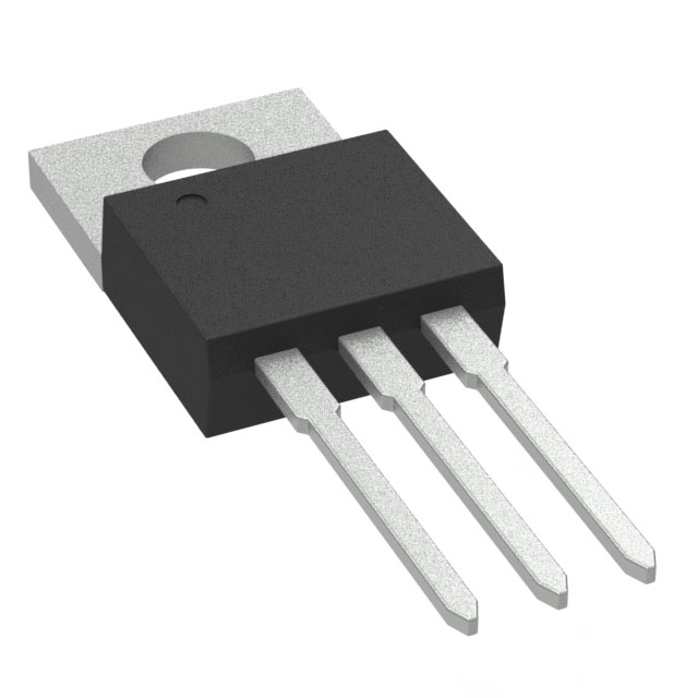
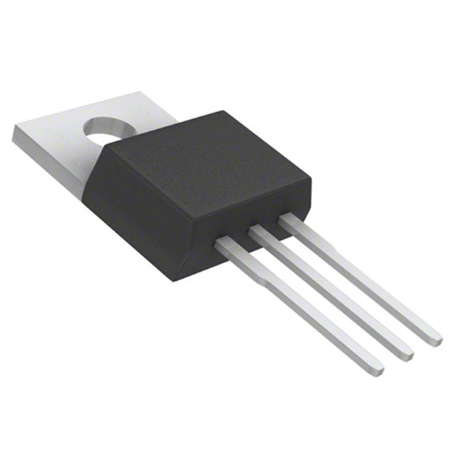
FDP3652 N-Channel MOSFET 100V 9A/61A TO-220-3 Equivalent & Substitute Parts
Part Overview
The FDP3652 is an N-Channel MOSFET manufactured by onsemi, rated for 100V drain-to-source voltage with continuous drain current of 9A at Ta and 61A at Tc. This device is packaged in TO-220-3 through-hole configuration and belongs to the PowerTrench® series. The FDP3652 carries a product status of "Not For New Designs," indicating that onsemi has discontinued active development and support for this component. Identifying equivalent and substitute parts is necessary for ongoing maintenance, repair, and redesign of legacy systems, as well as for new applications requiring comparable electrical and thermal performance characteristics.
Substiute Parts
Key Parameters
| Parameter | Value | Unit |
|---|---|---|
| Drain-to-Source Voltage (Vdss) | 100 | V |
| Continuous Drain Current @ 25°C (Id) | 9A (Ta), 61A (Tc) | A |
| On-Resistance (Rds On) @ 61A, 10V | 16 | mOhm |
| Gate Threshold Voltage (Vgs(th)) @ 250µA | 4 | V |
| Gate Charge (Qg) @ 10V | 53 | nC |
| Power Dissipation (Max) | 150 | W |
| Operating Temperature Range | -55 to 175 | °C |
| Package Type | TO-220-3 | — |
| Mounting Type | Through Hole | — |
| FET Type | N-Channel | — |
Substitute Part Grouping Explanation
Substitution of the FDP3652 is determined by strict alignment of the following electrical and mechanical parameters:
Primary Substitution Criteria:
- Drain-to-Source Voltage (Vdss): Must equal or exceed 100V
- FET Type: Must be N-Channel
- Package/Case: Must be TO-220-3 or compatible through-hole TO-220 variant
- Mounting Type: Must be Through Hole
- Operating Temperature Range: Must span -55°C to 175°C or equivalent
- Continuous Drain Current (Id): Must support minimum 61A at Tc or equivalent thermal condition
Secondary Compatibility Parameters:
- On-Resistance (Rds On): Lower values indicate improved performance; values within 12–23 mOhm range are functionally compatible
- Gate Charge (Qg): Values between 22–182 nC are acceptable for switching applications
- Power Dissipation: Minimum 71W; higher ratings provide thermal margin
- Gate Threshold Voltage (Vgs(th)): Range of 2.4V to 4.5V is compatible with standard gate drive circuits
Substitute parts listed below meet all primary criteria and fall within acceptable ranges for secondary parameters. Parts with "Active" product status are preferred for new applications; "Obsolete" parts are suitable for legacy system replacement only.
Parameter Comparison
| Parameter | FDP3652 (onsemi) | CSD19534KCS (TI) | IPP147N12N3GXKSA1 (Infineon) | IPP180N10N3GXKSA1 (Infineon) | IPP70N10S3L12AKSA1 (Infineon) | PSMN013-100PS,127 (Nexperia) | PSMN015-100P,127 (Nexperia) | PSMN016-100PS,127 (Nexperia) | STP45N10F7 (STMicroelectronics) | STP60NF10 (STMicroelectronics) | STP80NF10 (STMicroelectronics) |
|---|---|---|---|---|---|---|---|---|---|---|---|
| Vdss (V) | 100 | 100 | 120 | 100 | 100 | 100 | 100 | 100 | 100 | 100 | 100 |
| Id @ Tc (A) | 61 | 100 | 56 | 43 | 70 | 68 | 75 | 57 | 45 | 80 | 80 |
| Rds On (mOhm) | 16 @ 61A, 10V | 16.5 @ 30A, 10V | 14.7 @ 56A, 10V | 18 @ 33A, 10V | 12.1 @ 70A, 10V | 13.9 @ 15A, 10V | 15 @ 25A, 10V | 16 @ 15A, 10V | 18 @ 22.5A, 10V | 23 @ 40A, 10V | 15 @ 40A, 10V |
| Vgs(th) (V) | 4 @ 250µA | 3.4 @ 250µA | 4 @ 61µA | 3.5 @ 33µA | 2.4 @ 83µA | 4 @ 1mA | 4 @ 1mA | 4 @ 1mA | 4.5 @ 250µA | 4 @ 250µA | 4 @ 250µA |
| Qg (nC) | 53 @ 10V | 22.2 @ 10V | 49 @ 10V | 25 @ 10V | 80 @ 10V | 59 @ 10V | 90 @ 10V | 49 @ 10V | 25 @ 10V | 104 @ 10V | 182 @ 10V |
| Power Dissipation (W) | 150 | 118 | 107 | 71 | 125 | 170 | 300 | 148 | 60 | 300 | 300 |
| Package | TO-220-3 | TO-220-3 | PG-TO220-3 | PG-TO220-3 | PG-TO220-3-1 | TO-220AB | TO-220AB | TO-220AB | TO-220 | TO-220 | TO-220 |
| Operating Temp (°C) | -55 to 175 | -55 to 175 | -55 to 175 | -55 to 175 | -55 to 175 | -55 to 175 | -55 to 175 | -55 to 175 | -55 to 175 | Not specified | -55 to 175 |
| Product Status | Not For New Designs | Active | Active | Active | Active | Obsolete | Obsolete | Obsolete | Active | Active | Active |
| RoHS3 Compliant | Yes | Yes | Yes | Yes | Yes | Yes | Yes | Yes | Yes | Yes | Yes |
Engineering Selection Recommendations
For Active Product Status (Preferred for New Designs):
The following substitute parts carry "Active" product status and are recommended for new applications and long-term system designs:
-
CSD19534KCS (Texas Instruments): Meets all primary electrical criteria with 100V Vdss and 100A continuous drain current. Provides superior current handling and lower gate charge (22.2 nC) for faster switching. RoHS3 compliant. Suitable for high-current applications requiring thermal margin.
-
IPP147N12N3GXKSA1 (Infineon OptiMOS™): Rated for 120V Vdss, exceeding the 100V requirement. Delivers 56A continuous drain current with optimized on-resistance of 14.7 mOhm. Gate charge of 49 nC matches FDP3652 characteristics. Active product status with full manufacturer support.
-
IPP180N10N3GXKSA1 (Infineon OptiMOS™): Maintains 100V Vdss with 43A continuous drain current. Lower power dissipation (71W) suitable for applications with thermal constraints. Gate charge of 25 nC enables efficient switching. Active status with ongoing support.
-
IPP70N10S3L12AKSA1 (Infineon OptiMOS™): Provides 100V Vdss with 70A continuous drain current, exceeding FDP3652 performance. Superior on-resistance of 12.1 mOhm reduces conduction losses. Power dissipation of 125W provides thermal margin. Active product status.
-
STP45N10F7 (STMicroelectronics STripFET™ VII): Rated for 100V Vdss with 45A continuous drain current. Gate charge of 25 nC enables rapid switching. Power dissipation of 60W suitable for moderate-power applications. Active product status with full support.
-
STP60NF10 (STMicroelectronics STripFET™ II): Delivers 100V Vdss with 80A continuous drain current. High power dissipation rating of 300W provides substantial thermal margin. On-resistance of 23 mOhm is acceptable for applications prioritizing current capacity. Active product status.
-
STP80NF10 (STMicroelectronics STripFET™ II): Rated for 100V Vdss with 80A continuous drain current. Superior on-resistance of 15 mOhm reduces conduction losses compared to STP60NF10. Power dissipation of 300W supports high-power applications. Active product status with full manufacturer support.
For Obsolete Product Status (Legacy System Replacement Only):
The following parts carry "Obsolete" product status and are suitable only for replacement in existing systems where the FDP3652 is already deployed:
-
PSMN013-100PS,127 (Nexperia TrenchMOS™): Provides 100V Vdss with 68A continuous drain current. Power dissipation of 170W exceeds FDP3652. On-resistance of 13.9 mOhm is favorable. Obsolete status limits use to legacy applications.
-
PSMN015-100P,127 (Nexperia TrenchMOS™): Rated for 100V Vdss with 75A continuous drain current. Highest power dissipation rating of 300W among Nexperia options. On-resistance of 15 mOhm is competitive. Obsolete status restricts to replacement applications.
-
PSMN016-100PS,127 (Nexperia): Delivers 100V Vdss with 57A continuous drain current. Power dissipation of 148W is comparable to FDP3652. On-resistance of 16 mOhm matches FDP3652 specification. Obsolete status limits applicability.
Compliance and Certification:
All listed substitute parts are RoHS3 compliant and REACH unaffected, meeting environmental and regulatory requirements equivalent to the FDP3652. All parts operate across the -55°C to 175°C temperature range or equivalent, ensuring thermal compatibility in legacy and new applications.
Frequently Asked Questions (FAQ)
Q: Can I directly replace FDP3652 with any of the listed substitute parts?
A: Direct replacement is possible only if the substitute part meets all primary criteria: 100V minimum Vdss, N-Channel FET type, TO-220-3 or compatible through-hole package, and -55°C to 175°C operating range. All listed parts satisfy these requirements. However, verify that the application circuit can accommodate differences in gate charge, on-resistance, and power dissipation characteristics.
Q: What is the difference between TO-220-3, TO-220AB, and PG-TO220-3 packages?
A: All three are through-hole TO-220 variants with identical pin configurations and mechanical footprints. TO-220-3 is the standard designation. TO-220AB is an alternative designation used by some manufacturers. PG-TO220-3 and PG-TO220-3-1 are Infineon's proprietary package designations for their OptiMOS™ series but maintain full mechanical and electrical compatibility with standard TO-220-3 footprints. PCB layout and heatsink mounting are interchangeable across all variants.
Q: Why is the FDP3652 marked "Not For New Designs"?
A: This status indicates that onsemi has discontinued active development and support for this component. Existing inventory remains available, but the manufacturer does not recommend its use in new product designs. For new applications, select substitute parts with "Active" product status, such as CSD19534KCS, IPP147N12N3GXKSA1, or STP80NF10, which receive ongoing manufacturer support and design updates.
Q: How do I choose between substitute parts with different current ratings?
A: Select a substitute part based on your application's maximum continuous drain current requirement. If your circuit draws 50A at Tc, any substitute rated for 50A or higher is acceptable. Parts with higher current ratings (such as CSD19534KCS at 100A or STP80NF10 at 80A) provide thermal margin and reduce on-resistance losses. Parts with lower ratings (such as IPP180N10N3GXKSA1 at 43A) are suitable only if your application's maximum current does not exceed their rating.
Q: What is the significance of on-resistance (Rds On) differences?
A: On-resistance determines conduction losses in the FET. Lower Rds On values reduce power dissipation and heat generation. The FDP3652 specifies 16 mOhm at 61A and 10V. Substitute parts range from 12.1 mOhm (IPP70N10S3L12AKSA1) to 23 mOhm (STP60NF10). For high-current applications, select parts with lower Rds On to minimize thermal stress. For low-current applications, Rds On differences have minimal impact.
Q: Can I use a substitute part rated for 120V (such as IPP147N12N3GXKSA1) in a 100V application?
A: Yes. A higher voltage rating provides additional safety margin and does not degrade performance in lower-voltage applications. The 120V rating of IPP147N12N3GXKSA1 is fully compatible with 100V circuits. This approach is acceptable for both legacy replacement and new designs.
Q: What does gate charge (Qg) mean, and why does it vary among substitutes?
A: Gate charge is the total charge required to switch the FET from off to on state. Higher gate charge requires more current from the gate driver circuit and increases switching time. The FDP3652 specifies 53 nC. Substitutes range from 22.2 nC (CSD19534KCS) to 182 nC (STP80NF10). If your gate driver has limited current capacity, select parts with lower gate charge. If gate driver current is not constrained, higher gate charge values are acceptable.
Q: Are Nexperia parts (PSMN series) suitable for new designs?
A: No. All Nexperia parts listed (PSMN013-100PS,127, PSMN015-100P,127, PSMN016-100PS,127) carry "Obsolete" product status. These parts are suitable only for replacement in existing systems where they are already deployed. For new designs, select parts with "Active" status from Texas Instruments, Infineon, or STMicroelectronics.
Q: What is the difference between Ta and Tc current ratings?
A: Ta refers to continuous drain current at ambient temperature (typically 25°C). Tc refers to continuous drain current at case temperature (typically 25°C with thermal management). The FDP3652 specifies 9A at Ta and 61A at Tc, indicating that thermal management significantly increases current capacity. When selecting substitutes, use the Tc rating for applications with adequate heatsinking and the Ta rating for applications without active cooling.
Q: Can I use multiple lower-current MOSFETs in parallel to replace the FDP3652?
A: Parallel operation of MOSFETs is possible but requires careful circuit design to ensure equal current distribution. This approach is outside the scope of direct substitution and requires detailed analysis of gate drive circuits, PCB layout, and thermal management. For simplicity and reliability, select a single substitute part rated for the required current.
Q: What compliance certifications should I verify before selecting a substitute?
A: All listed substitute parts are RoHS3 compliant and REACH unaffected, matching the FDP3652 certifications. Verify that your application requirements do not mandate additional certifications (such as automotive-grade qualification or specific military standards). If such requirements exist, consult the detailed datasheets of candidate substitute parts or contact the manufacturer directly.
Alternative Parts

SJ6012L2TP
Littelfuse Inc.
6 Alternative Parts

JMK107BBJ476MA-RE
Taiyo Yuden
10 Alternative Parts

GMK107BBJ475MA-T
Taiyo Yuden
5 Alternative Parts
SJ6020N2ARP
Littelfuse Inc.
3 Alternative Parts
SJ6025R2ATP
Littelfuse Inc.
4 Alternative Parts

2474-05L
API Delevan Inc.
1 Alternative Parts

4590R-684K
API Delevan Inc.
1 Alternative Parts

CM6560R-334
API Delevan Inc.
1 Alternative Parts

CM6460-104
API Delevan Inc.
1 Alternative Parts

5526-12
API Delevan Inc.
1 Alternative Parts