


Request Quote
(Ships tomorrow)
DGD21084S14-13 Equivalent & Substitute Parts
Part Overview
The DGD21084S14-13 is a half-bridge gate driver IC manufactured by Diodes Incorporated, designed for driving IGBT and N-Channel MOSFET configurations in power management applications. This device operates with a supply voltage range of 10V to 20V and features independent dual-channel architecture with non-inverting input logic.
The DGD21084S14-13 is classified as obsolete. Identifying suitable substitute components is necessary to maintain design continuity, ensure supply chain reliability, and support ongoing production requirements for applications utilizing this gate driver topology.
Substiute Parts
Key Parameters
| Parameter | Value |
|---|---|
| Driven Configuration | Half-Bridge |
| Channel Type | Independent |
| Number of Drivers | 2 |
| Gate Type | IGBT, N-Channel MOSFET |
| Voltage - Supply | 10V ~ 20V |
| Logic Voltage - VIL, VIH | 0.6V, 2.5V |
| Current - Peak Output (Source, Sink) | 200mA, 600mA |
| Input Type | Non-Inverting |
| High Side Voltage - Max (Bootstrap) | 600V |
| Rise / Fall Time (Typ) | 100ns, 35ns |
| Operating Temperature | -40°C ~ 150°C (TJ) |
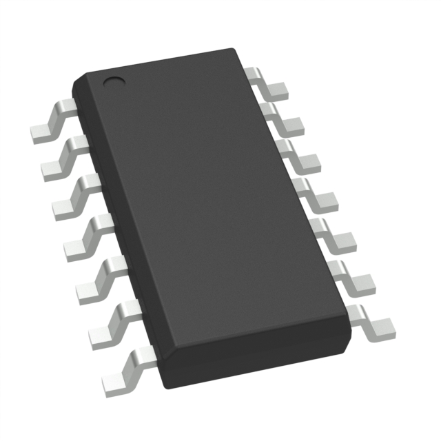
| Package / Case | 14-SOIC (0.154", 3.90mm Width) |
| RoHS Status | ROHS3 Compliant |
| Moisture Sensitivity Level (MSL) | 3 (168 Hours) |
Substitute Part Grouping Explanation
Substitution of the DGD21084S14-13 is determined by strict equivalence across the following critical parameters:
- Driven Configuration: Half-Bridge topology must be maintained
- Channel Type & Number of Drivers: Independent dual-channel architecture required
- Gate Type: IGBT and N-Channel MOSFET compatibility mandatory
- Supply Voltage Range: 10V ~ 20V operation required
- Logic Voltage Levels: VIL 0.6V, VIH 2.5V must be matched
- Input Type: Non-Inverting logic required
- Bootstrap Voltage Rating: 600V maximum rating required
- Rise / Fall Time: 100ns rise, 35ns fall time specifications
- Compliance: ROHS3 and REACH compliance required
The LF2106NTR from IXYS Integrated Circuits Division meets all substitution criteria within these defined parameters.
Parameter Comparison
| Parameter | DGD21084S14-13 | LF2106NTR | Compatibility |
|---|---|---|---|
| Manufacturer | Diodes Incorporated | IXYS Integrated Circuits Division | Different manufacturer |
| Driven Configuration | Half-Bridge | Half-Bridge | Match |
| Channel Type | Independent | Independent | Match |
| Number of Drivers | 2 | 2 | Match |
| Gate Type | IGBT, N-Channel MOSFET | IGBT, N-Channel MOSFET | Match |
| Voltage - Supply | 10V ~ 20V | 10V ~ 20V | Match |
| Logic Voltage - VIL, VIH | 0.6V, 2.5V | 0.6V, 2.5V | Match |
| Current - Peak Output (Source, Sink) | 200mA, 600mA | 290mA, 600mA | LF2106NTR exceeds source current |
| Input Type | Non-Inverting | Non-Inverting | Match |
| High Side Voltage - Max (Bootstrap) | 600V | 600V | Match |
| Rise / Fall Time (Typ) | 100ns, 35ns | 100ns, 35ns | Match |
| Operating Temperature | -40°C ~ 150°C (TJ) | -40°C ~ 125°C (TA) | LF2106NTR has narrower range |
| Package / Case | 14-SOIC (0.154", 3.90mm Width) | 8-SOIC (0.154", 3.90mm Width) | Different pin count |
| RoHS Status | ROHS3 Compliant | ROHS3 Compliant | Match |
| Moisture Sensitivity Level (MSL) | 3 (168 Hours) | 3 (168 Hours) | Match |
| Product Status | Obsolete | Active | Substitute is active |
Engineering Selection Recommendations
The LF2106NTR qualifies as a functional substitute for the DGD21084S14-13 based on equivalence across all critical electrical parameters: supply voltage, logic levels, gate type compatibility, bootstrap voltage rating, and switching characteristics.
Key considerations for selection:
Electrical Compatibility: The LF2106NTR provides peak source current of 290mA compared to the DGD21084S14-13 specification of 200mA, representing a performance enhancement. Sink current remains equivalent at 600mA. Both devices maintain identical rise and fall time specifications of 100ns and 35ns respectively.
Temperature Operating Range: The DGD21084S14-13 operates to 150°C junction temperature, while the LF2106NTR operates to 125°C ambient temperature. Applications requiring operation above 125°C ambient require thermal analysis to confirm junction temperature compliance.
Package Consideration: The DGD21084S14-13 uses 14-SOIC packaging while the LF2106NTR uses 8-SOIC packaging. PCB layout modifications are required for pin-compatible substitution.
Compliance Status: Both devices maintain ROHS3 compliance and identical moisture sensitivity ratings, supporting equivalent supply chain and manufacturing requirements.
Product Availability: The LF2106NTR maintains active product status with current inventory availability, addressing the obsolescence of the DGD21084S14-13.
Frequently Asked Questions (FAQ)
Q: Can the LF2106NTR directly replace the DGD21084S14-13 without PCB modifications?
A: No. The DGD21084S14-13 uses 14-SOIC packaging while the LF2106NTR uses 8-SOIC packaging. PCB layout redesign is required to accommodate the different pin configuration and package footprint.
Q: Are the logic voltage thresholds identical between these devices?
A: Yes. Both the DGD21084S14-13 and LF2106NTR specify VIL of 0.6V and VIH of 2.5V, ensuring compatible signal interpretation in non-inverting gate driver applications.
Q: Does the higher peak source current of the LF2106NTR affect circuit design?
A: The LF2106NTR provides 290mA peak source current versus 200mA for the DGD21084S14-13. This represents improved performance capability. Existing circuit designs rated for 200mA source current will operate within the LF2106NTR specification envelope.
Q: What is the temperature operating range difference between these parts?
A: The DGD21084S14-13 specifies -40°C to 150°C junction temperature operation. The LF2106NTR specifies -40°C to 125°C ambient temperature operation. Applications requiring sustained operation above 125°C ambient require thermal modeling to confirm junction temperature remains within the LF2106NTR limit.
Q: Are both devices RoHS compliant?
A: Yes. Both the DGD21084S14-13 and LF2106NTR are ROHS3 compliant with identical moisture sensitivity level ratings of 3 (168 Hours).
Q: What are the key electrical parameters that must match for substitution?
A: Critical matching parameters include: half-bridge driven configuration, independent dual-channel architecture, 10V to 20V supply voltage range, 0.6V/2.5V logic thresholds, non-inverting input type, 600V bootstrap voltage rating, and 100ns/35ns rise/fall time specifications.
Alternative Parts

SJ6012L2TP
Littelfuse Inc.
6 Alternative Parts

JMK107BBJ476MA-RE
Taiyo Yuden
10 Alternative Parts

GMK107BBJ475MA-T
Taiyo Yuden
5 Alternative Parts
SJ6020N2ARP
Littelfuse Inc.
3 Alternative Parts
SJ6025R2ATP
Littelfuse Inc.
4 Alternative Parts

2474-05L
API Delevan Inc.
1 Alternative Parts

4590R-684K
API Delevan Inc.
1 Alternative Parts

CM6560R-334
API Delevan Inc.
1 Alternative Parts

CM6460-104
API Delevan Inc.
1 Alternative Parts

5526-12
API Delevan Inc.
1 Alternative Parts