


Request Quote
(Ships tomorrow)
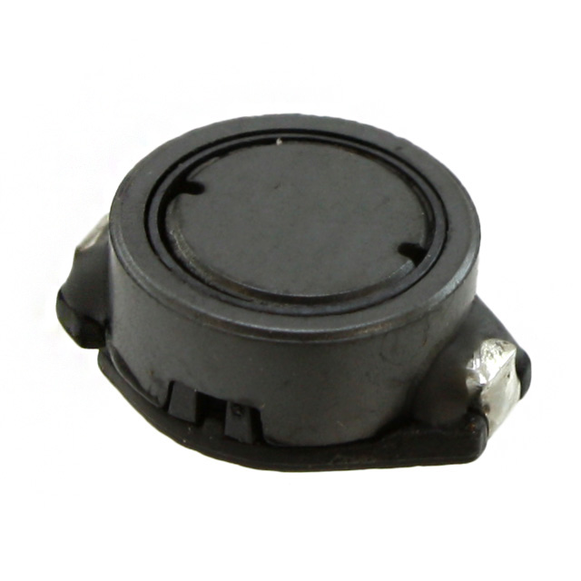
CDRR94ANP-181MC Equivalent & Substitute Parts
Part Overview
The CDRR94ANP-181MC is a 180 µH shielded inductor manufactured by Sumida America Components Inc., rated for 540 mA continuous current with a maximum DC resistance of 784.8 mOhm. This surface mount component features a ferrite core and is designed for applications requiring controlled inductance in compact form factors.
The CDRR94ANP-181MC is classified as obsolete. Identifying equivalent substitute parts is necessary to maintain design continuity, ensure supply chain availability, and support ongoing production requirements for systems utilizing this inductor specification.
Substiute Parts
Key Parameters
| Parameter | Value | Unit |
|---|---|---|
| Inductance | 180 | µH |
| Inductance Tolerance | ±20% | — |
| Current Rating (Continuous) | 540 | mA |
| Current - Saturation (Isat) | 600 | mA |
| DC Resistance (DCR) Maximum | 784.8 | mOhm |
| Shielding | Shielded | — |
| Core Material | Ferrite | — |
| Operating Temperature Range | -40°C to 100°C | — |
| Mounting Type | Surface Mount | — |
| Physical Dimensions (L × W) | 12.90 × 9.40 | mm |
| Height - Seated (Maximum) | 5.00 | mm |
| RoHS Status | ROHS3 Compliant | — |
| Moisture Sensitivity Level (MSL) | 1 (Unlimited) | — |
Substitute Part Grouping Explanation
Substitution of the CDRR94ANP-181MC is determined by strict equivalence across the following critical parameters:
Primary Equivalence Criteria:
- Inductance value: 180 µH (tolerance range acceptable within design margins)
- Shielding classification: Shielded construction required
- Core material: Ferrite core
- Mounting type: Surface mount configuration
- Current rating: Minimum 540 mA continuous current capability
- DC resistance: Maximum 784.8 mOhm or lower
- Operating temperature range: Minimum -40°C to 100°C coverage
- RoHS compliance: ROHS3 Compliant
Secondary Compatibility Factors:
- Physical footprint compatibility within PCB layout constraints
- Saturation current (Isat) rating: Minimum 600 mA
- Packaging format: Surface mount compatible
The substitute part SRR1005-181K meets all primary equivalence criteria and is classified as an active product, providing supply chain continuity for the obsolete CDRR94ANP-181MC.
Parameter Comparison
| Parameter | CDRR94ANP-181MC (Main Part) | SRR1005-181K (Substitute) | Compatibility Assessment |
|---|---|---|---|
| Manufacturer | Sumida America Components Inc. | Bourns Inc. | Different manufacturer, equivalent specification |
| Inductance | 180 µH | 180 µH | Exact match |
| Inductance Tolerance | ±20% | ±10% | Substitute offers tighter tolerance |
| Current Rating (Continuous) | 540 mA | 500 mA | Substitute rated 40 mA lower; verify application margin |
| Current - Saturation (Isat) | 600 mA | 650 mA | Substitute exceeds specification |
| DC Resistance (DCR) Maximum | 784.8 mOhm | 700 mOhm | Substitute offers lower resistance |
| Shielding | Shielded | Shielded | Exact match |
| Core Material | Ferrite | Ferrite | Exact match |
| Core Type | Standard | Drum Core, Wirewound | Different construction; equivalent electrical performance |
| Operating Temperature Range | -40°C to 100°C | -40°C to 125°C | Substitute offers extended upper temperature limit |
| Mounting Type | Surface Mount | Surface Mount | Exact match |
| Physical Dimensions (L × W) | 12.90 × 9.40 mm | 12.70 × 10.00 mm | Dimensions within typical PCB layout tolerance |
| Height - Seated (Maximum) | 5.00 mm | 5.20 mm | Height difference 0.20 mm; verify clearance |
| RoHS Status | ROHS3 Compliant | ROHS3 Compliant | Exact match |
| Moisture Sensitivity Level (MSL) | 1 (Unlimited) | 1 (Unlimited) | Exact match |
| Product Status | Obsolete | Active | Substitute ensures ongoing availability |
Engineering Selection Recommendations
Substitution Feasibility:
The SRR1005-181K is a qualified substitute for the CDRR94ANP-181MC based on electrical parameter equivalence and active product status. Both components are ROHS3 compliant and MSL 1 rated, meeting regulatory and environmental requirements.
Critical Considerations:
-
Current Rating Differential: The SRR1005-181K is rated for 500 mA continuous current versus 540 mA for the CDRR94ANP-181MC. Applications operating at or above 500 mA require thermal and current margin analysis to confirm the substitute is suitable for the intended duty cycle.
-
Physical Footprint: Dimensional differences (length 12.70 mm vs. 12.90 mm; width 10.00 mm vs. 9.40 mm; height 5.20 mm vs. 5.00 mm) are within typical surface mount component tolerances. PCB layout verification is required to confirm clearance and placement compatibility.
-
DC Resistance: The SRR1005-181K exhibits lower DC resistance (700 mOhm maximum versus 784.8 mOhm maximum), resulting in reduced power dissipation and improved efficiency.
-
Temperature Range: The SRR1005-181K supports extended operating temperature to 125°C, providing additional thermal margin for applications with elevated ambient conditions.
-
Inductance Tolerance: The SRR1005-181K offers ±10% tolerance versus ±20% for the CDRR94ANP-181MC, enabling tighter circuit performance specifications.
Compliance Status:
Both components satisfy ROHS3 and MSL 1 requirements. The SRR1005-181K active product status ensures long-term supply chain availability and technical support.
Frequently Asked Questions (FAQ)
Q1: Can the SRR1005-181K directly replace the CDRR94ANP-181MC without PCB modifications?
A: The SRR1005-181K is electrically equivalent for the 180 µH inductance specification. Physical dimensions differ slightly (maximum 0.20 mm height difference, 0.20 mm length difference, 0.60 mm width difference). PCB layout verification is required to confirm component placement clearance and trace routing compatibility. No circuit modifications are necessary if physical clearance is confirmed.
Q2: What is the impact of the 40 mA lower current rating on the SRR1005-181K?
A: The SRR1005-181K is rated for 500 mA continuous current versus 540 mA for the CDRR94ANP-181MC. Applications operating below 500 mA experience no impact. For applications requiring 500–540 mA operation, thermal analysis of the substitute component under actual duty cycle conditions is necessary to confirm adequate current margin and temperature rise limits.
Q3: Are there differences in electromagnetic shielding effectiveness between these components?
A: Both components are classified as shielded inductors with ferrite cores. Specific shielding effectiveness data (attenuation characteristics, frequency response) is not provided in the component specifications. For applications with critical EMI/RFI requirements, electromagnetic performance testing or manufacturer consultation is recommended.
Q4: How do the inductance tolerances affect circuit performance?
A: The CDRR94ANP-181MC specifies ±20% inductance tolerance; the SRR1005-181K specifies ±10%. The tighter tolerance of the substitute may improve circuit performance in applications sensitive to inductance variation. Circuit designs accounting for ±20% tolerance will operate within specification with the ±10% substitute.
Q5: What is the significance of the different core construction (standard vs. drum core wirewound)?
A: The CDRR94ANP-181MC uses standard ferrite core construction; the SRR1005-181K uses drum core wirewound construction. Both achieve the same 180 µH inductance specification with equivalent electrical performance. The different construction methods result in comparable DC resistance, saturation current, and operating characteristics suitable for direct substitution.
Q6: Is the extended temperature range of the SRR1005-181K (-40°C to 125°C) a significant advantage?
A: The SRR1005-181K supports operation to 125°C versus 100°C for the CDRR94ANP-181MC. This extended range provides additional thermal margin for applications in elevated ambient environments or with restricted thermal dissipation. For applications operating within -40°C to 100°C, both components are equivalent.
Q7: What packaging format is the SRR1005-181K supplied in?
A: The SRR1005-181K is supplied in Tape & Reel (TR) format, standard for high-volume surface mount assembly. The CDRR94ANP-181MC packaging format is not specified in the provided data. Confirm packaging compatibility with assembly equipment and procurement processes.
Q8: Are both components suitable for lead-free soldering processes?
A: Both components are ROHS3 compliant, indicating compatibility with lead-free soldering processes and materials. MSL 1 rating for both components indicates unlimited shelf life and no moisture sensitivity concerns for standard storage and handling conditions.
Alternative Parts

SJ6012L2TP
Littelfuse Inc.
6 Alternative Parts

JMK107BBJ476MA-RE
Taiyo Yuden
10 Alternative Parts

GMK107BBJ475MA-T
Taiyo Yuden
5 Alternative Parts
SJ6020N2ARP
Littelfuse Inc.
3 Alternative Parts
SJ6025R2ATP
Littelfuse Inc.
4 Alternative Parts

2474-05L
API Delevan Inc.
1 Alternative Parts

4590R-684K
API Delevan Inc.
1 Alternative Parts

CM6560R-334
API Delevan Inc.
1 Alternative Parts

CM6460-104
API Delevan Inc.
1 Alternative Parts

5526-12
API Delevan Inc.
1 Alternative Parts