


Request Quote
(Ships tomorrow)
1008HC-273EKFS Equivalent & Substitute Parts
Part Overview
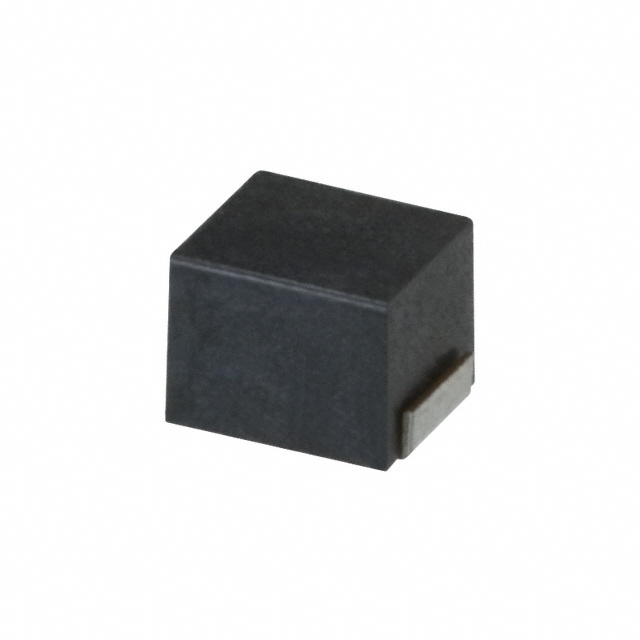
The 1008HC-273EKFS is a 27 µH unshielded drum core wirewound inductor manufactured by Delta Electronics/Components, designed for surface mount applications in the 1008 (2520 Metric) package. This component operates at 180 mA current rating with 3.4Ω DC resistance and is characterized by a self-resonant frequency of 17 MHz.
The 1008HC-273EKFS carries an obsolete product status. Identifying equivalent substitute parts is necessary to maintain design continuity, ensure supply chain availability, and support ongoing production requirements for applications utilizing this inductor specification.
Substiute Parts
Key Parameters
| Parameter | Value |
|---|---|
| Inductance | 27 µH |
| Inductance Tolerance | ±10% |
| Current Rating | 180 mA |
| DC Resistance (DCR) | 3.4Ω |
| Core Type | Ferrite Drum Core, Unshielded |
| Package / Case | 1008 (2520 Metric) |
| Mounting Type | Surface Mount |
| Operating Temperature Range | -40°C ~ 85°C |
| Self-Resonant Frequency | 17 MHz |
| RoHS Status | ROHS3 Compliant |
Substitute Part Grouping Explanation
Substitute parts for the 1008HC-273EKFS are identified based on the following critical parameters that define functional equivalence:
Primary Matching Criteria:
- Inductance value: 27 µH (matching specification)
- Package / Case: 1008 (2520 Metric) (identical physical footprint)
- Core type: Ferrite drum core, unshielded (same magnetic architecture)
- Mounting type: Surface mount (same assembly method)
- Test frequency: 2.52 MHz (same measurement standard)
Secondary Compatibility Parameters:
- Operating temperature range overlap
- RoHS3 compliance status
- Current rating and DC resistance within acceptable application limits
The NLV25T-270J-EF from TDK Corporation qualifies as a substitute based on matching inductance, package, core type, and mounting specifications. Differences in current rating, DC resistance, and operating temperature range must be evaluated against specific application requirements.
Parameter Comparison
| Parameter | 1008HC-273EKFS (Delta) | NLV25T-270J-EF (TDK) |
|---|---|---|
| Inductance | 27 µH | 27 µH |
| Inductance Tolerance | ±10% | ±5% |
| Current Rating (Amps) | 180 mA | 115 mA |
| DC Resistance (DCR) | 3.4Ω | 6.3Ω Max |
| Core Material | Ferrite | Ferrite |
| Shielding | Unshielded | Unshielded |
| Q @ Freq | 20 @ 2.52MHz | 25 @ 2.52MHz |
| Self-Resonant Frequency | 17 MHz | 21 MHz |
| Operating Temperature | -40°C ~ 85°C | -40°C ~ 105°C |
| Package / Case | 1008 (2520 Metric) | 1008 (2520 Metric) |
| Mounting Type | Surface Mount | Surface Mount |
| RoHS Status | ROHS3 Compliant | ROHS3 Compliant |
| Product Status | Obsolete | Active |
Engineering Selection Recommendations
Substitution Feasibility:
The NLV25T-270J-EF is suitable as a substitute for the 1008HC-273EKFS based on matching inductance value, package footprint, core architecture, and mounting method. Both components are ROHS3 compliant and operate within overlapping temperature ranges.
Critical Considerations for Application Integration:
-
Current Rating Differential: The NLV25T-270J-EF has a maximum current rating of 115 mA compared to the original 180 mA specification. Applications requiring current levels between 115 mA and 180 mA must be re-evaluated for thermal and performance impact.
-
DC Resistance Increase: The substitute part exhibits 6.3Ω maximum DC resistance versus 3.4Ω in the original component. This represents an 85% increase in resistive losses, affecting power dissipation and circuit efficiency.
-
Inductance Tolerance: The NLV25T-270J-EF provides tighter tolerance (±5%) compared to the original (±10%), which may improve circuit performance consistency.
-
Temperature Operating Range: The substitute supports extended upper temperature operation (105°C versus 85°C), providing additional thermal margin in high-temperature environments.
-
Product Status: The NLV25T-270J-EF maintains active product status with established supply chain availability, addressing the obsolescence issue of the original component.
Compliance Status:
Both components satisfy ROHS3 requirements. The NLV25T-270J-EF is REACH Affected, while the original is REACH Unaffected. Regulatory compliance verification is required based on end-application jurisdiction.
Frequently Asked Questions (FAQ)
Q: Can the NLV25T-270J-EF directly replace the 1008HC-273EKFS without circuit modification?
A: Direct physical replacement is possible due to identical package dimensions and footprint. However, circuit performance must be re-evaluated due to differences in current rating, DC resistance, and inductance tolerance. Applications operating at currents above 115 mA or requiring the lower DC resistance of the original component require design adjustment.
Q: What is the impact of the increased DC resistance on circuit operation?
A: The 6.3Ω maximum DC resistance of the NLV25T-270J-EF compared to 3.4Ω of the original results in higher resistive losses. In applications where the inductor carries significant current, this increases power dissipation and heat generation. Thermal analysis of the specific application is necessary to determine acceptability.
Q: Are both components compatible with the same PCB assembly process?
A: Yes. Both components use identical 1008 (2520 Metric) surface mount packaging and are suitable for standard reflow soldering processes. Physical dimensions are similar, with the NLV25T-270J-EF slightly smaller in length and width.
Q: What is the significance of the inductance tolerance difference?
A: The NLV25T-270J-EF provides ±5% tolerance compared to ±10% for the original. This tighter tolerance reduces inductance variation across production batches, improving circuit consistency and reducing performance spread in applications sensitive to inductance value.
Q: Does the extended operating temperature range of the substitute affect reliability?
A: The NLV25T-270J-EF supports operation to 105°C versus 85°C for the original. This extended range provides additional thermal margin and may improve reliability in elevated-temperature environments. Applications operating within the original 85°C limit experience no adverse effect.
Q: How should current rating differences be handled in circuit design?
A: Applications utilizing the original 1008HC-273EKFS at currents between 115 mA and 180 mA must be re-evaluated. Either reduce operating current to 115 mA maximum, select an alternative inductor with higher current rating, or implement additional thermal management. Current derating analysis is required for safe substitution.
Q: Are there supply chain advantages to using the NLV25T-270J-EF?
A: Yes. The NLV25T-270J-EF maintains active product status with established inventory availability. The original 1008HC-273EKFS is obsolete, making the substitute the practical choice for ongoing production and future procurement.
Alternative Parts

SJ6012L2TP
Littelfuse Inc.
6 Alternative Parts

JMK107BBJ476MA-RE
Taiyo Yuden
10 Alternative Parts

GMK107BBJ475MA-T
Taiyo Yuden
5 Alternative Parts
SJ6020N2ARP
Littelfuse Inc.
3 Alternative Parts
SJ6025R2ATP
Littelfuse Inc.
4 Alternative Parts

2474-05L
API Delevan Inc.
1 Alternative Parts

4590R-684K
API Delevan Inc.
1 Alternative Parts

CM6560R-334
API Delevan Inc.
1 Alternative Parts

CM6460-104
API Delevan Inc.
1 Alternative Parts

5526-12
API Delevan Inc.
1 Alternative Parts